
How A CNC Press Brake For Automotive Metal Works: Robot Bending Guide
CNC press brake for automotive metal production is moving toward one clear target: stable bend quality at higher speed, with less operator pressure. In automotive work, a small angle shift may look harmless at the press brake, yet it can turn into a fit-up headache later—especially when parts must match jigs, fixtures, welded assemblies, or robotic welding programs. When flange length drifts, downstream stations slow down. When angles vary, assembly gaps show up. When rework grows, throughput collapses.
At JS RAGOS, we build press brake bending cells that combine an advanced CNC press brake with robotic automation. The point is not “automation for show.” It is an industrial method to keep geometry under control—shift after shift—while your team spends less time measuring, re-bending, and firefighting. This guide explains the bending robot concept in a beginner-friendly way, then links each capability to real automotive outcomes.
What a Bending Robot Is and What It Can Do
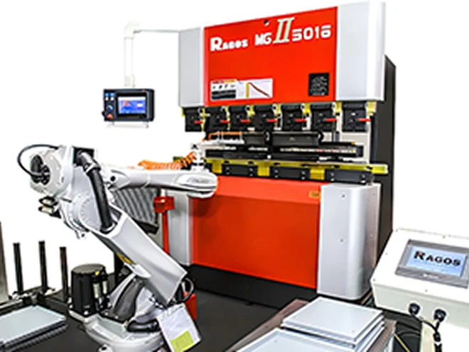
A bending robot is a programmable system that automates how a sheet is positioned, presented, and managed during bending. It can perform simple V-bends, but it is most valuable when parts need multiple steps that would normally depend on operator experience. In automotive metal works, this matters because product volume is often high, part families are broad, and consistency is more valuable than “one perfect part.”
A robotic bending cell reduces variation by standardizing the steps that usually create mistakes: handling, alignment, timing, and re-positioning. Once you validate a program, the system repeats the same sequence with the same motion logic. That makes results easier to predict—and easier to plan around.
✅ Key capabilities you can expect from a robotic bending system:
✓ Multi-angle bending for brackets, mounts, housings, reinforcements, and enclosure-like parts
✓ Material flexibility across different thicknesses and part geometries
✓ Higher throughput by reducing manual positioning, measuring, and re-bending
✓ Stable repeatability that reduces scrap and rework
When your bending step becomes predictable, the next steps—welding, riveting, fastening, inspection, and final assembly—stop absorbing your schedule buffer. That is why a CNC press brake for automotive metal paired with a robot cell often improves the entire line, not just the bending station.
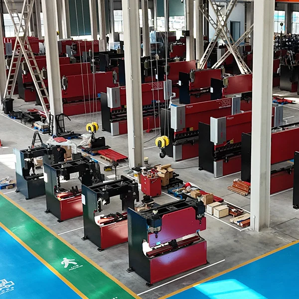
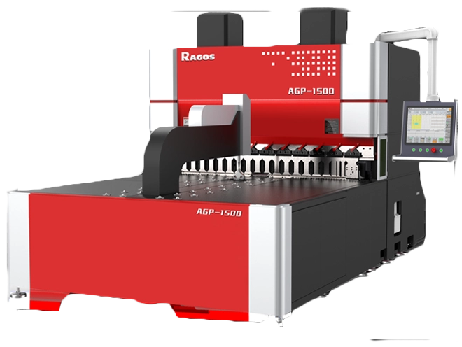
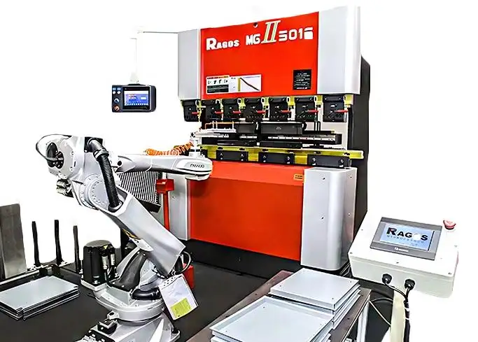
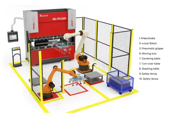
The Core Components Inside a Modern Bending Cell
A robotic bending system is not only a robot arm. It is a coordinated “cell” where every component supports accuracy, flow, and safety. At JS RAGOS, we design the cell around customer drawings and real production constraints, because the correct cell is not defined by a brochure. It is defined by how your parts behave.
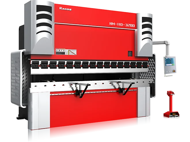
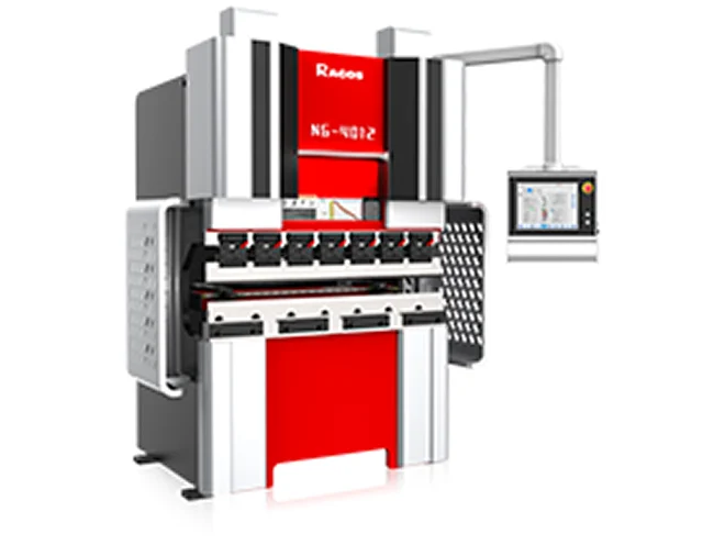
Robot, Press Brake, and Controls Working as One
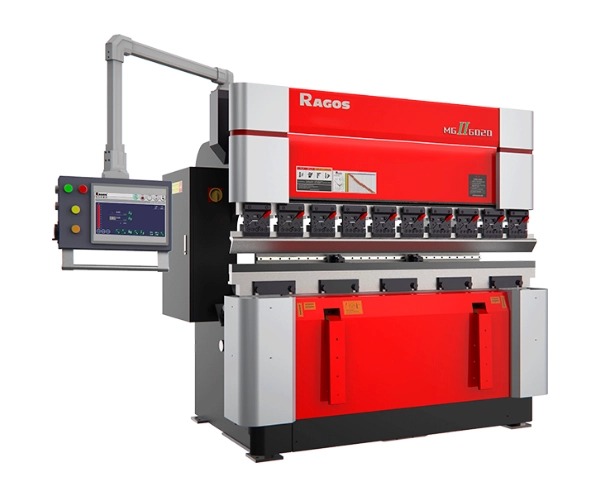
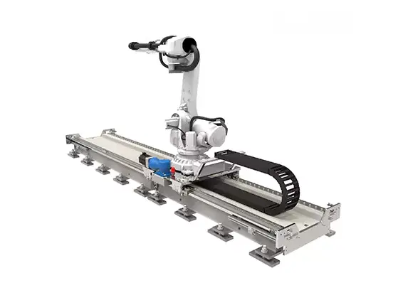
A typical JS RAGOS cell can support multi-brand robots such as FANUC, KUKA, ABB, and Yaskawa, paired with intelligent CNC systems such as DELEM, ESA, and Cybelec. For a customer, this is not about brand names. It is about integration and continuity. You can align the robot and controller ecosystem with what your plant already runs, so training is simpler and maintenance planning is clearer.
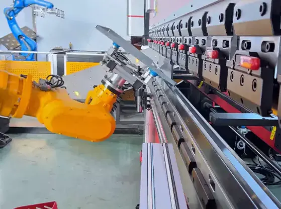
Tooling and clamping are also decisive, especially in automotive work where surfaces may be coated, visible, or prone to scratching. We can configure the cell with high-quality tooling and clamping systems such as Wila, Amada, and Rolleri, plus specialized fixtures when parts require tighter handling or anti-scratch protection. The practical benefit is that tool stability becomes repeatable, which helps keep flange length and angle results more stable over long runs.
Layout That Improves Flow and Reduces Handling
A well-designed bending cell layout protects cycle time and reduces “hidden labor,” such as walking, lifting, and frequent re-positioning. Common stations include:
✓ Loading Plate for raw sheets
✓ Alignment Table to position sheets for accurate bends
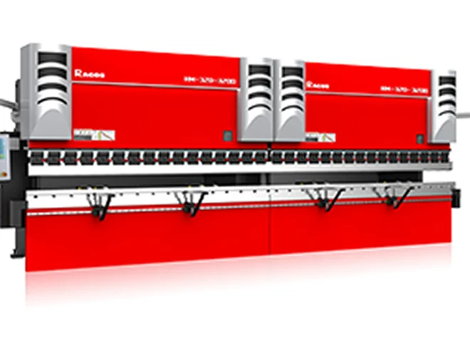
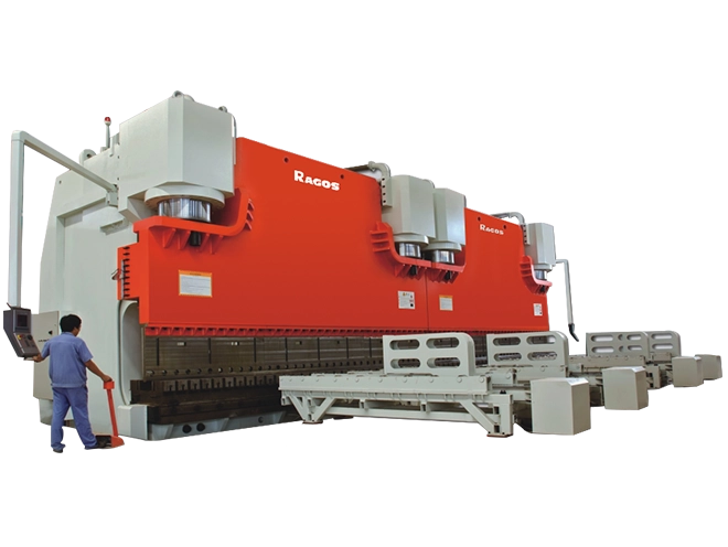
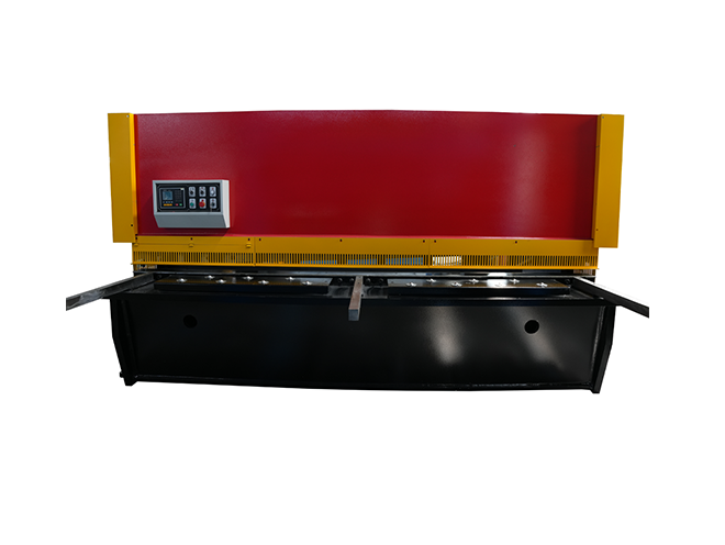
✓ Bending Area with the press brake
✓ Flipping/Rotating Table for multi-side bends
✓ Unloading Plate for finished parts
✓ Floor Cabinets for organized tooling and accessories
A clean layout does two things at once: it shortens each cycle and lowers the chance of positioning errors. In automotive production, those two gains often matter more than peak-tonnage claims, because real output is usually limited by handling and alignment.
How a Robotic Press Brake Bending Cycle Works
Robotic bending looks complex at first, but the workflow is logical. Once the program, tools, and gripping plan are ready, the cell runs a repeatable sequence. The system does not “guess.” It follows a defined path.
✅ A basic bending cycle includes:
✓ Load: The operator or automation loads a flat sheet onto the work area. Clamps or fixtures keep it stable.
✓ Align: Guided by CAD/CAM logic, the robot positions the sheet so each bend occurs at the correct line and orientation.
✓ Bend: The robot presents the part to the press brake. The machine applies controlled force to reach the target angle.
✓ Reposition (If Needed): For complex parts, the system rotates or flips the workpiece to access different bend directions.
✓ Unload: The finished part is placed on the unloading station for inspection or next-step processing.
To support multi-bend parts, many cells include a regrip station / repositioning station. A flipping or rotating table reduces manual handling and helps keep the part aligned for second- and third-side bends. In automotive work, where multiple flanges and tight clearances are common, this station can be the difference between “possible” and “repeatable.” It also reduces the chance of surface damage because the part is not repeatedly lifted and dragged by hand.
If you are evaluating a CNC press brake for automotive metal automation project, this is a simple test: ask how the cell will handle the part between bends, not only how it will perform the first bend.
Precision, Safety, and Quality Control Features That Reduce Scrap
In automotive metal works, quality problems often appear as angle variation, springback inconsistency, and part-to-part mismatch. A robot cell reduces these issues by making bending controlled and measurable, and by reducing the number of “manual judgment moments” inside the cycle.
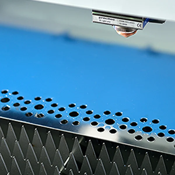
Angle Measurement That Corrects Springback
For customers who need tighter control, JS RAGOS can integrate a laser-assisted bend angle measurement system that checks angles after a single bending operation. The published performance includes accuracy exceeding ±0.1°, and the system can automatically compensate for springback by measuring the real angle and correcting bending parameters.
On the shop floor, the value is direct: fewer test bends, fewer adjustments, and fewer “almost good” parts that fail later during fit-up. If your line runs multiple materials or thicknesses, this kind of feedback also helps stabilize results across variation that would otherwise force operators to “feel” their way through production.
Safety Systems Designed for Real Press Brake Risk
Automation does not remove safety requirements—it changes them. Light curtains and laser-based protection help protect operators and prevent accidents around the bending zone. A moving protection zone concept can stop motion if an obstacle enters the protected area.
The practical benefit is not only compliance. It is confidence. Teams work faster when safety logic is clear, predictable, and correctly integrated into the cycle. When operators trust the cell, they spend less time hesitating and more time supervising production.
Automotive Applications and How JS RAGOS Helps You Scale
Robotic bending is a strong fit for automotive parts because the industry rewards repeatable output, stable geometry, and predictable cost per part. Common examples include body brackets, reinforcement components, exhaust-related sheet assemblies, structural mounts, and enclosure-like parts that require multiple bends with consistent geometry.
At JS RAGOS, we also provide targeted automation building blocks that help customers scale without losing control:
✓ 7-Axis Bending Robot for higher flexibility and longer workpiece handling
✓ Future Scalability so the cell can handle more parts as demand increases
✓ Flexible Positioning, allowing the robot to move aside so operators can manually bend additional parts when required
✓ Custom End-Of-Arm Grippers tailored to your parts—engineered for scratch-free handling, stable pickup, and fast cycles, from thin sheet to heavier assemblies
✓ 3D Offline Software supporting major robot brands, with features such as automatic gripping and path calculation, interactive adjustment, support for vacuum or clamp grippers, rail systems, stacking setup, and synchronized CNC code for both robot and machine
These features are not “extra technology.” They are practical tools that reduce setup time, stabilize output, and protect surface quality—especially important when parts are visible, coated, or must fit precisely in assemblies.
When customers ask what makes a bending cell successful, our answer is simple: it must protect three realities at once—geometry, surface condition, and cycle time. That is the real reason a CNC press brake for automotive metal robot cell matters.
✅ CTA: Request a Quote From JS RAGOS
If you want a CNC press brake for automotive metal bending cell designed from your drawings—robot brand, controller, tooling, gripper, layout, and safety included—contact JS RAGOS to Request A Quote. We will help you choose a bending cell configuration that fits your parts today and scales cleanly for tomorrow.