


What Is Bend Allowance? 2026 CNC Press Brake Wholesale Quick Guide
CNC press brake wholesale projects often stumble for one predictable reason: the flat pattern was estimated instead of engineered. In 2026, fabrication teams run shorter lead times, more part revisions, and tighter fit-up requirements. That makes bend math a daily skill, not a “wall chart” secret. At JS RAGOS, we build press brakes for repeatable bending, and we teach the fundamentals that help new CAD/CAM and CNC programmers protect material yield, avoid rework, and keep delivery schedules stable.
Why Bend Allowance Is the Small Number That Controls Big Costs
Bend Allowance is the length of the arc through the bend area, measured along the neutral axis—the layer inside the material that does not stretch or compress during bending. This definition matters because unfolding is not about the inside surface or the outside surface. Unfolding is about the neutral axis path.
In practical terms, Bend Allowance is what turns a 3D part into a flat pattern that actually matches the finished bend. When that number is wrong, the failure is not subtle. Flanges come out short, hole locations drift, and assemblies require forcing or shimming. When Bend Allowance is right, your first article becomes a confirmation, not a correction.
For many CNC press brake wholesale buyers, Bend Allowance is a quiet profitability driver. It directly influences scrap rate, cycle time, and how confidently you can quote jobs without padding.
✅ Fewer first-article scrapped blanks
✅ Better fit-up across batches and operators
✅ More stable quoting because rework drops
The Core Concepts Beginners Must Master First
A beginner does not need dozens of formulas. They need a small set of terms that explain what the sheet is doing in the bend zone. Once these are clear, the math becomes logical.
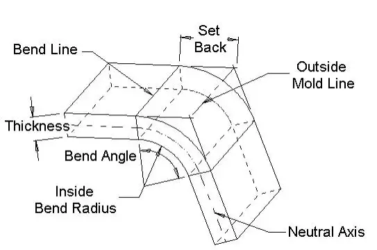
• Neutral Axis: The theoretical layer where material length does not change in the bend.
• K-Factor: The location of the neutral axis expressed as a percentage of thickness.
• Inside Bend Radius: The radius on the inside surface of the bend area.
• Mold Line: Where the extended flange surfaces intersect (where drawings often dimension).
• Setback: The distance from bend lines to the mold line.
Among these, K-factor is the concept that separates guesswork from controlled results. K-factor is not a single “correct” value for every job. It shifts with material behavior and bending method. Harder materials compress less on the inside and stretch more on the outside, pushing the neutral axis closer to the inside. A smaller bend radius increases the need for compression, also moving the neutral axis inward.
✅ Softer materials → neutral axis stays closer to the center
✅ Harder materials → neutral axis moves toward the inside
✅ Smaller radius → more compression, neutral axis shifts inward
This is also why experienced teams standardize tooling and bending methods whenever possible. The more consistent the process, the more consistent the neutral axis behavior becomes.
Bend Allowance Formula, Made Practical
Many online resources show “different” Bend Allowance equations, but most are the same relationship written with different shortcuts. A widely used working form is:
Bend Allowance = Angle × (π / 180) × (Radius + K-Factor × Thickness)
The first term converts degrees to radians. The second term, (Radius + K × Thickness), is the effective radius of the arc at the neutral axis. This is the point many beginners miss: the neutral axis is not on the inside radius and not on the outside surface. It sits somewhere inside the thickness, and K-factor describes where.
A Simple L-Bracket Example You Can Copy
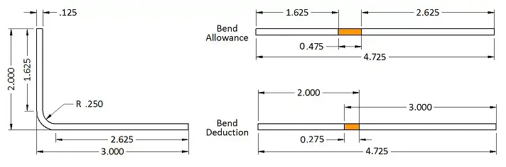
To show how clean this can be, use the example below:
• Two legs: 2 in and 3 in
• Thickness: 0.125 in
• Inside radius: 0.250 in
• Bend angle: 90°
• K-factor: 0.42
Now calculate:
Bend Allowance = 90 × (π / 180) × (0.250 + 0.42 × 0.125) = 0.475 in
Then your flat pattern length is the sum of flange lengths plus one Bend Allowance for the bend zone. In this example, the final flat length becomes 4.725 in.
This is why CNC press brake wholesale onboarding should include at least one worked example. A single accurate example prevents weeks of trial parts and “mystery” dimensional drift.
Mold Line Drawings: Why Bend Compensation Can Be Easier
Most real shop drawings do not dimension to tangent points. They dimension to flange intersections—also called mold lines. That is normal, but it changes how you should think about unfolding.
If you build your flat pattern from mold line dimensions, Bend Compensation is often more convenient. It allows you to keep the dimensions you see on the drawing and apply one adjustment per bend.
Two common relationships are:
Bend Compensation = Bend Allowance – (2 × Setback)
Setback = tan(Angle / 2) × (Radius + Thickness)
This explains a classic beginner confusion: a part that “looks like” 5 in on the outside mold-line dimensions may unfold to 4.725 in after the bend geometry is accounted for. That difference is not an error. It is the correction your flat pattern needs to match the finished part. In the example above, the compensation is -0.275, so 5.000 in becomes 4.725 in after subtraction.
✅ Use Bend Allowance when you build from tangent points
✅ Use Bend Compensation when you build from mold lines
✅ Choose one method and standardize it across CAD/CAM
Standardization is not only a programming preference. It is a quality system. When different programmers use different assumptions, you get inconsistent blanks that look “almost right” until assembly day.
2026 Production Shortcut: Coefficient Tables for Speed and Consistency
In modern shops, speed matters. That is why many CNC press brake wholesale customers use a blended workflow: learn the theory, then apply coefficient tables to move faster without losing control.
Coefficient tables connect three practical variables:
• Lower die V opening
• Plate thickness
• A bending factor (often shown as P’ or similar)
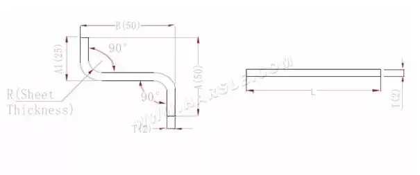
One reference case shows:
• Plate thickness: 2.0 mm
• Lower die: V12
A two-bend unfolding example:
• L = A + T + B – 2 × P’
• With P’ = 3.4, the expanded length becomes 95.2 for the given dimensions.
Used correctly, tables are not “cheating.” They are a shop’s way of packaging bend geometry into a repeatable coefficient tied to tooling and thickness. The condition is important: tables work best when the process is consistent. If you keep changing die openings or mixing bending methods, your coefficient assumptions stop matching reality.
✅ Faster programming under delivery pressure
✅ Less variation across shifts and operators
✅ Best results when tooling and materials are standardized
If you are training a new programmer, a strong teaching order is: definitions → one formula example → when to use compensation → how tables relate to tooling.
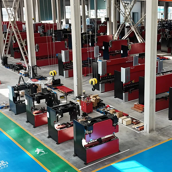
Why JS RAGOS Helps CNC Press Brake Wholesale Buyers Bend With Confidence
Bend math delivers value only when the machine can reproduce the assumptions. Machine stability is what turns calculations into parts. Consistent angles and radii keep your Bend Allowance or Bend Compensation results accurate, helping you reduce scrap and rework.
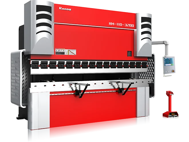
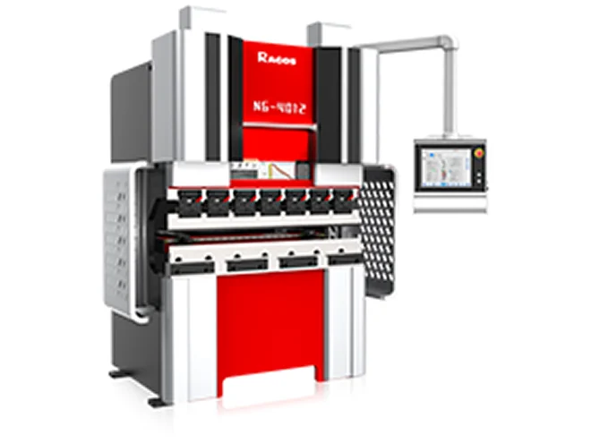
At JS RAGOS, we provide CNC press brake wholesale solutions designed to protect your production efficiency. Our goal is to help you reduce uncertainty in the first article and maintain accuracy in production runs.
✅ Repeatable bending behavior that reduces angle drift, so you spend less time “chasing” corrections
✅ Programming-friendly support so your CAD/CAM team can standardize one unfolding method and train faster
✅ Shop-ready calculation resources such as bend allowance and bend deduction style tools to speed up quoting and first checks
✅ Wholesale supply capability for distributors and integrators who need consistent machine configurations across sites
A press brake should not force your team to compensate for instability with extra scrap and extra inspection. The machine should support the process you want: predictable unfolding, predictable bends, and predictable delivery.
CTA: If you are evaluating CNC press brake wholesale units for 2026 and want fewer flat-pattern surprises, contact JS RAGOS. Share your common materials, thickness range, and typical bend angles. We will recommend a practical setup and provide a beginner-friendly calculation reference that aligns tooling selection with predictable unfolding results.