


Metal Sheet Bending Machine Manufacturer Guide to Press Brake Crowning
Metal Sheet Bending Machine Manufacturer JS RAGOS presents a practical guide to press brake crowning for consistent, high-accuracy bending.
Why Crowning Matters in Precision Bending
In sheet metal production, the press brake is only as accurate as its ability to resist deflection. During bending, reaction forces concentrate toward the ends of the ram while the central span bows. The ram's lower surface becomes slightly concave, and the gap between punch and die tightens in the middle. The result is a long part with angle variation along its length: tighter angles at mid-span, open angles at the ends. This is the pain point that leads to rework, shimming, extra trial bends, and tool wear.
Crowning compensates by creating a controlled, upward elastic deformation in the lower table that mirrors the ram's deflection curve. When crowning is correctly matched to load and length, the die opening remains uniform from left to right, and the angle stays linear. For a Metal Sheet Bending Machine Manufacturer, this is not a feature; it is a process capability that drives throughput and first-pass yield.
As a manufacturer, JS RAGOS sees three recurring issues on customer floors:
•Inconsistent angles across long profiles that require hand re-bending.
•Excessive setup time due to manual shimming and guesswork.
•Drift in accuracy during the shift as material thickness, heat, or tool wear change the load.
A well-chosen crowning system addresses these issues by restoring a predictable geometry under load and enabling repeatable, data-driven adjustments.
Hydraulic Vs Mechanical Crowning: a Metal Sheet Bending Machine Manufacturer Perspective
- Hydraulic Crowning in Practice
Hydraulic crowning uses a series of oil cylinders integrated beneath the lower table. Cylinder position and capacity follow the expected deflection profile derived from structural analysis. Under CNC command, a proportional hydraulic valve meters pressure to each cylinder group. The pistons extend a small amount, flexing the main table upward within its elastic range. Because the lower table remains a single plane at contact, the sheet is stably supported as the ram closes.
From a Metal Sheet Bending Machine Manufacturer perspective, hydraulic crowning delivers several clear benefits:
•No wedge or screw wear in the crowning element; the table flexes elastically.
•Compact integration with minimal added height and width.
•Stable plane contact with the workpiece, reducing the risk of sheet displacement.
•Adjustment is possible with the part still clamped, enabling quick corrections between bends.
When changeovers are frequent and part families vary in length and thickness, the ability to adapt pressure profiles quickly saves time and protects accuracy.
- Mechanical Crowning in Practice
Mechanical crowning relies on a matched set of inclined wedge blocks arranged under the table. The wedge geometry follows the machine's deflection curve, also derived from structural analysis. A dedicated CNC axis drives the wedges laterally. As the wedges shift, the stack creates a "pre-bulge” along the table, aligning the die gap before load is fully applied. With multiple contact points across the length, the compensation follows a precise curve, and the machine bends in a more linear mode.
Key advantages recognized by JS RAGOS include:
•Long-term stability with a rigid, purely mechanical stack that is effectively maintenance-free over the service life when designed and lubricated correctly.
•Many crowning points along the table length, enabling fine, distributed compensation.
•Digital positioning under CNC control, using feedback to set and verify the crowning axis.
The mechanical approach avoids hydraulic oil, hoses, or seals. Over very long use, screws or wedges can exhibit wear, but robust materials and proper preload extend life and keep accuracy stable.
- Choosing Between the Two
The correct choice depends on production context more than on theory. JS RAGOS recommends aligning the crowning system to your operating realities:
•Product mix: Frequent changeovers and diverse materials favor hydraulic flexibility. Stable, repeatable runs favor mechanical consistency.
•Floor space and height limits: Hydraulic packs are typically more compact.
•Service philosophy: Mechanical avoids hydraulic maintenance; hydraulic avoids wedge wear.
•Part length and tonnage: Very long beds and high tonnage benefit from dense crowning points; both systems can be engineered accordingly.
•Process control: Both integrate as a CNC axis; confirm your controller supports crowning tables and per-job offsets.
•Environmental constraints: Where oil management is challenging, mechanical offers a clean alternative.
*the working principles of hydraulic Crowning and mechanical Crowning are explained
by taking DA-66T series numerical control system of DELEM Company in the Netherlands as an example.
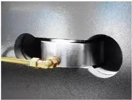
①Working principle of hydraulic Crowning
The following flow chart is a control schematic diagram taking
DELEN DA-66T numerical control system and HO-ERBIGER hydraulic system as examples.
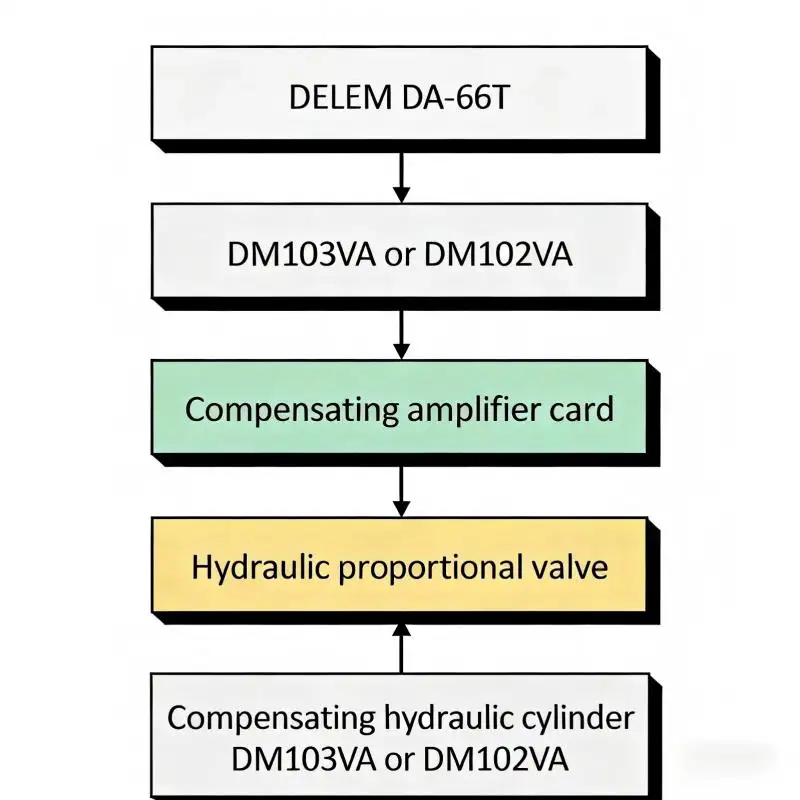
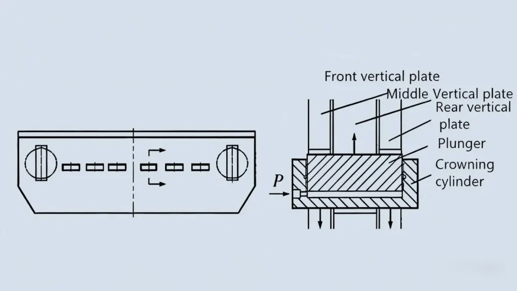
In the figure below, the table's underside uses a stiff central plate with lighter side plates; the center is intentionally higher where the crowning cylinder mounts. As the part is bent, the CNC computes crowning and modulates a proportional valve to supply the crowning cylinder with oil. The piston's small extension elastically lifts the center plate, improving dimensional accuracy. Proper CNC parameter setup is equally important.
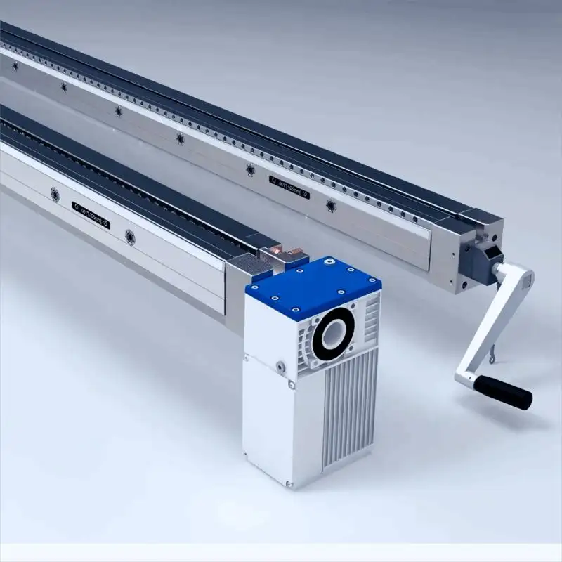
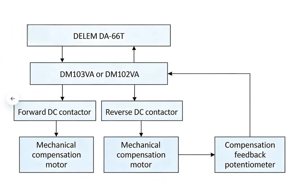
②The working principle of mechanical Crowning
Selection and Calibration Guidance from JS RAGOS
- JS RAGOS Crowning Options and Engineering Approach
As a Metal Sheet Bending Machine Manufacturer, JS RAGOS supplies both hydraulic and mechanical crowning engineered around the machine's real deflection curve. Our hydraulic systems employ grouped cylinders sized and positioned to the structure's elastic response, with closed-loop valve control and sealed manifolds for stable pressure delivery. Our mechanical systems use precision-ground wedge modules that form a continuous curve when engaged, driven by a CNC crowning axis for accurate, repeatable positioning.
Across both approaches, we emphasize:
•Elastic deformation within the table's safe range to protect long-term geometry.
•Crowning maps stored per tool, material, and length to reduce trial time.
•Integration with the CNC so operators can load the job, confirm the crowning value, and run with confidence.
- Setup and Calibration Essentials
Getting crowning right is a method, not guesswork. The following practices reflect what JS RAGOS trains on site:
•Establish a baseline: Use a straight, representative test piece near full bed length. Verify angle at left, center, and right with calibrated gauges.
•Zero correctly: Start with the crowning axis at its known zero, and ensure the punch and die are clean and properly seated.
•Match the curve, not just the center: If the center is tight and ends are open, increase crowning along the curve; if ends are tight, reduce crowning.
•Keep the work clamped when fine-tuning: With hydraulic crowning, adjust pressure while the part remains in position to remove one variable from the system. For mechanical systems, apply small, recorded increments and re-strike if needed.
• Use consistent process data: Set the CNC with correct material thickness, width, and die opening so load calculations are valid for the crowning table.
• Validate and store: Once angles are uniform along length, store the crowning value with the job. Repeat validation for new batches or material lots.
- Production Pain Points Crowning Solves
•Angle variation along long flanges that drives secondary rework.
•Time lost to manual shimming under the die and undocumented offsets.
•Variation over shift due to tool heating and material spread.
•Operator-dependent outcomes that hinder repeatability.
By replacing reactive fixes with a predictable crowning profile, plants see higher first-pass yield, fewer test bends, and more stable takt.
How JS RAGOS Helps You Decide
Every factory's loading cases differ. JS RAGOS performs an application review that includes expected bed length usage, typical tonnage, material spectrum, and target tolerances. From there, we propose hydraulic or mechanical crowning with the right density of compensation points and the right control integration. For many mixed-model shops, hydraulic crowning offers rapid adaptability and in-process adjustability. For dedicated, high-volume lines, mechanical crowning provides a stable, wear-resistant foundation with fine distributed compensation.
Call to Action
If your team is battling angle variation, manual shims, or long setup times, partner with JS RAGOS. Request a no-obligation bending audit and crowning recommendation tailored to your parts and processes. Our engineers will benchmark your current results, define the optimal crowning strategy, and configure CNC integration so operators can run to target on the first bend. Contact JS RAGOS today to schedule an application review and elevate your press brake accuracy with a manufacturer's expertise.
With the right crowning system, selected and calibrated by a Metal Sheet Bending Machine Manufacturer that understands structural deflection and production realities, your press brakes deliver the linear angles, reduced rework, and throughput that modern sheet metal demands.