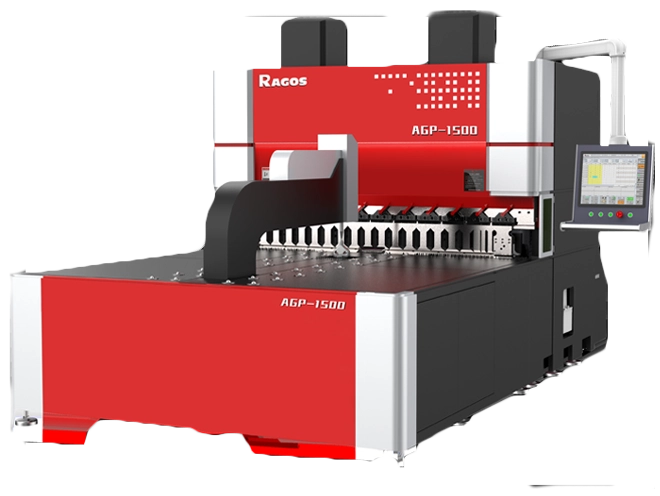


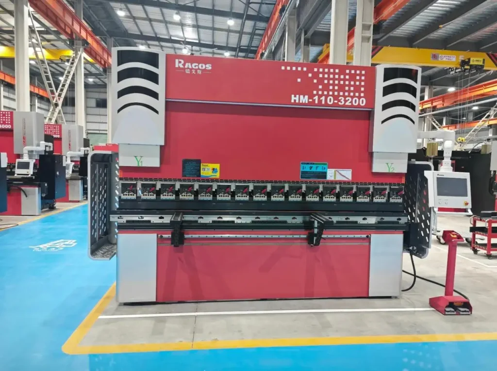
How to Adjust Bending Angle on Precision CNC Press Brake
Precision CNC Press Brake angle control defines part quality, throughput, and stable cost in metal fabrication. At JS RAGOS, we approach angle adjustment as a disciplined, repeatable process that blends machine capability with operator judgment. Our teams support prototype shops and short-run lines that need the first part right and the last part identical. The guidance below reflects practices we see working every day on the factory floor.
Foundations of Angle Control on a Precision CNC Press Brake
Achieving a target bend angle starts with understanding how materials, tooling, and the press brake itself behave under load. Get these fundamentals right, and fine adjustments become fast and predictable.
Material and springback. Every sheet returns elastically after bending. Mild steel, stainless steel, and aluminum spring back by different amounts. Higher yield strength and greater thickness increase that return. Because air bending relies on angle vs. penetration, you must allow for springback. Plan for a small over-bend based on your material and V-opening, then verify with a test piece.
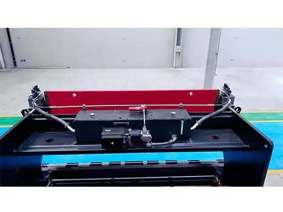
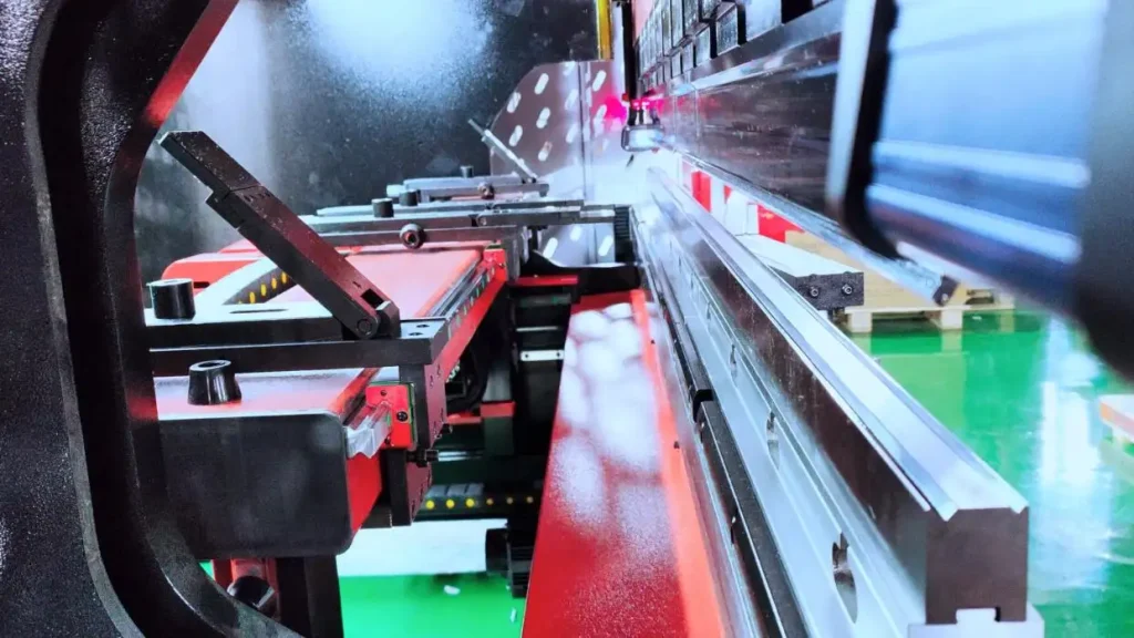
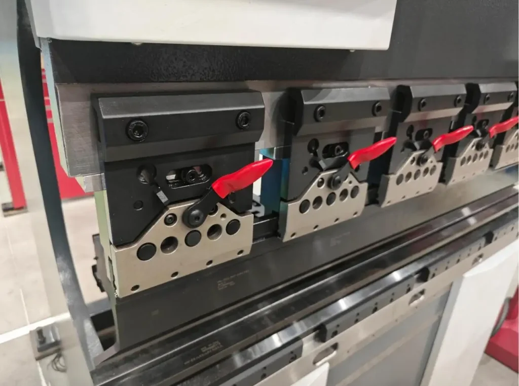
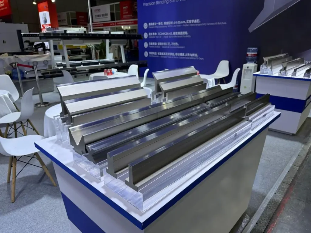
Tooling geometry. Tooling choice sets the baseline for angle control. For angles above 90°, a matched 90° upper and lower die typically offers a stable bend. For angles less than 90°, use V-shaped punches and dies to support the workpiece and control the line. When your goal is a crisp 90°, a 30° sharp punch with a 30° groove in the lower die can refine the bend line and reduce scatter. Precision-ground tools reduce gap variability and help the press brake deliver the angle you program.
Setup and alignment. Align the center of the upper and lower dies, then set an initial gap that slightly exceeds the sheet thickness. Approach the angle in small steps. Confirm that hydraulics and seals are sound; pressure instability becomes angle variation at the part.
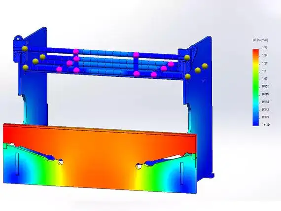
Deflection and crowning. Long parts flex the bed and ram. Without compensation, the center angle opens while the edges close. Use mechanical or CNC crowning to pre-load the bed so the punch penetration is uniform along the bend length. Crowning is essential for long, thin parts where uniformity matters.
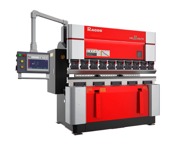
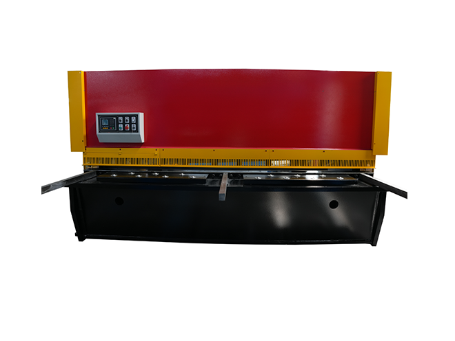
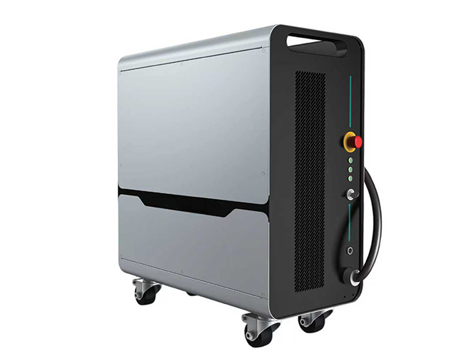
Machine repeatability. If your tolerance is ±1° and not negotiable, a high-precision CNC is the right tool. A Precision CNC Press Brake with slider repeatability around ±0.0004 inches makes that possible when paired with good tooling and process discipline. Manual press brakes often hold around ±0.002 inches on the slider, with typical angle deviations of ±2–3° even when the die set is appropriate. This gap explains why teams moving to tighter specs step up to CNC controls and structured setup methods.
A Practical Workflow to Adjust Bend Angle
A consistent workflow cuts trial-and-error and stabilizes quality. We recommend the sequence below as a baseline. Adapt it to your materials, tooling library, and part mix.
• Compute tonnage and set the V-opening. Reference thickness and bend length, then specify a lower die V that supports the sheet and controls springback. Confirm the Precision CNC Press Brake has sufficient capacity plus a buffer.
• Center and verify the tool stack. Seat both tools, align the punch and die centerlines, and check all stops. Return axes to origin. Put the workpiece at mid-span of the bed to obtain a stable initial pressure measurement.
• Set back gauge distance. Use electric quick adjustment for coarse positioning and the handwheel for fine trimming. When available, use the readout scale for repeatable increments - for example, 0.1 mm per handwheel revolution. Lock the gauge to avoid drift.
• Program slider travel and speed. Adjust the upper travel limit to achieve a TDC stop and eliminate unnecessary stroke. Use the travel switch and potentiometer to program a soft approach near the bend. The slower entry enhances angle control and minimizes marking.
• Execute a controlled test in single-step: press the foot pedal to advance, release to pause, press again to proceed. Staged motion allows early stop if needed and protects the sample.
• Measure the angle in a consistent routine with a calibrated gauge or digital protractor at the two ends and the middle. Record the displayed machine value and the measured angle so you can repeat settings later.
• Adjust punch penetration. On a Precision CNC Press Brake, bend angle is governed mainly by how deep the punch enters the V-groove. Adjust the handwheel or side runner in small increments. Do not drive the punch too deep at once; approach the target in controlled steps.
• Balance the cylinders. If the upper tool touches down unevenly, trim the opposing cylinder to synchronize both sides. Lightly press on the side reading the smaller angle, then set final depth. Concurrent contact limits torsion and keeps the angle consistent.
• Apply crowning and springback compensation. For long parts, set crowning before the second test. If the center angle is more open than the edges, increase crowning. Where springback is significant, program a small over-bend and verify the returned angle meets specification.
• Confirm repeatability after warm-up. Cycle two or three full strokes before finalizing settings. If angles fluctuate, recheck tool seating, back gauge rigidity, hydraulic pressure, and seal condition. Consistent mechanics yield consistent angles.
Once the workflow is stable, standardize measurement practice. Use the same gauge, at the same locations on the part, after the same dwell time. Keep a simple record: material grade and thickness, V-opening, displayed depth, measured angle, and any offset or over-bend applied. This record shortens future setups and raises first-pass yield.
Air bending versus bottoming deserves attention. Air bending is flexible and requires springback compensation; it is well suited for varied angles and short runs. Bottoming can lock angle more tightly at the cost of higher tonnage and potential surface marks. When surface appearance is critical, consider protective film and polished tooling, and test at production speed.
Angle control also depends on back gauge strategy. For tight flange tolerances, square the gauge to the die line and check for deflection on long fingers. When forming small flanges, support the part so it does not droop during the bend. A stable back gauge removes one variable from the angle equation and reduces the chance of rework.
From Pain Points to Production Gains with JS RAGOS
Shops tell us their biggest obstacles are angle drift across long parts, inconsistent springback between coils, downtime during frequent tool changes, and safety concerns during manual adjustment. Our Precision CNC Press Brake platform and support package are designed to remove these obstacles while preserving flexibility for short runs.
• High repeatability for tight angles. Our focus on frame stiffness, hydraulic stability, and feedback control targets slider repeatability around ±0.01 mm. In practice, this supports ±1° angle windows with quality tooling and a coherent setup routine.
• Rapid die setup. Quick-change Amada clamp and clear datum references reduce tool change time and shrink the “first-article variability” zone. Fast, positive seating helps the first bend match the last - no extended tweaking required.
• Crowning and process control embedded. Mechanical or CNC crowning keeps angles uniform along the bend length. Programmable slow zones near the point of contact safeguard surface quality and improve angle control on thin materials.
• Back gauge precision with speed. Coarse electric moves combined with manual fine trim let operators hit dimension quickly and then lock it in. Clear readouts simplify repeat jobs and reduce data entry errors.
• Structured calibration and training. We supply angle calibration routines, checklists, and short training modules that connect digital display values to real angles. Teams learn to document a bend once and repeat it confidently.
• Safety built into the routine. Footswitch logic, interlocks, and return-to-origin practices reduce risk during setup and adjustment. Stable motion translates directly into stable angles.
When the specification demands increase - new alloys, tighter bends, more frequent changeovers - the difference between a conventional brake and a Precision CNC Press Brake becomes tangible. Manual brakes, with slider repeatability near ±0.002 inches, often show ±2–3° angle spread even with proper tools. If you are losing time chasing those degrees, upgrading machine capability and standardizing your process are the fastest ways to recover margin.
At JS RAGOS, we help customers move from firefighting to control. The path is straightforward: validate the tooling library, set crowning rules by part length, fix measurement practice, and tie bend angles to displayed penetration in the control. With these foundations, operators spend less time adjusting and more time producing.
Call to Action
If your team is contending with angle scatter, rework, or slow changeovers, we can help. Request an application audit, a live angle-adjustment demo on a JS RAGOS Precision CNC Press Brake, or our bend angle checklist. We will review your materials, V-openings, and part mix, then propose a clear workflow and machine settings to hit specification with fewer trials and faster setup. Connect with JS RAGOS today and turn bend angles into a process you can trust.