


How To Perform Tooling Installation With A Press Brake Delem Controller
Having trouble with tooling setup on a press brake? A wrong entry in the control can slow production, affect bend accuracy, and create unnecessary rework. This guide explains how to complete tooling installation in a clear, practical way.
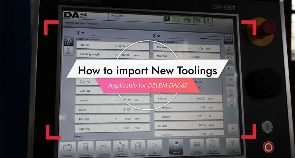
Dans cet article, JS RAGOS walks through the basic process of setting up punches and dies with a Press Brake Delem Controller. The goal is to keep the sequence close to real workshop practice: enter the upper tool first, review and finalize the tool profile, then add the lower die. For operators who are new to Delem controls, or for teams that want a cleaner setup routine, this process helps reduce mistakes and improve consistency on the shop floor.
Press Brake Delem Controller Tooling Installation Introduction
A modern Press Brake Delem Controller does more than store bend programs. It also helps the operator build an accurate tooling library, define punch and die geometry, and make sure the machine understands what is mounted on the press brake.
When tooling data is entered correctly, the controller can calculate bend positions more reliably, support smoother programming, and reduce the risk of setup errors. Whether you are replacing an existing tool, adding a new punch, or preparing a new die for production, the installation logic stays largely the same: measure carefully, input the correct values, review the geometry, and save the tool properly.
This guide follows that same path so the setup process feels easier to repeat in daily operation.
Pas 1: Add The Punches
The first stage is to add the upper tool, or punch. Since the punch directly affects bend angle, Pénétration, and forming quality, it must be entered with care.
1. Select The "Add New" Option
Start from the tooling area of the controller. Open the punch setup page and choose the option to add a new tool. This creates a new record where the punch data can be entered manually.
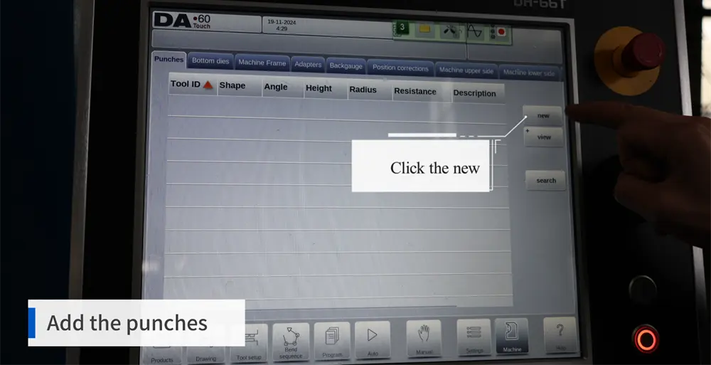
At this stage, the controller is waiting for the basic tool information. It is better to begin with a clean new entry than to overwrite an old one that may contain incorrect dimensions.
2. Enter Punch Name
Type in a clear name or identifier for the punch into the controller. Doing this may seem like a simple task, mais, it can be quite helpful when there are many punch profiles saved in one machine. A name can be used to help select one quickly and it can improve reliability.
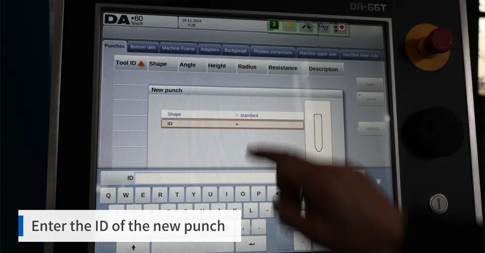
Some ideas for naming include:
•Tool type
•Working angle
•Radius
•Length or series identifier
Using a clear naming system can help operators better avoid mistakes when the same job needs to be done repeatedly, and when tools need to be replaced.
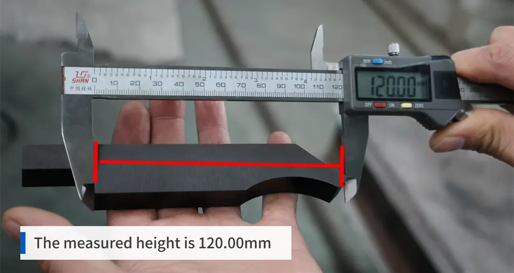
3. Measure Punch Height
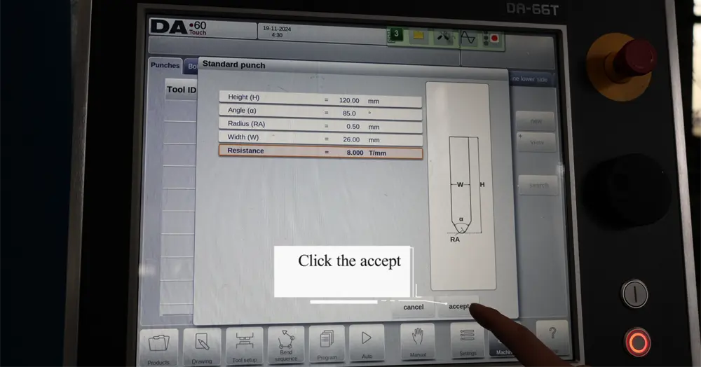
Now, take a measurement for the height of the punch using a caliper or another precision measuring device. For this example, the height of the punch is 120.00 mm.
This measurement is crucial since it determines how the controller will calculate the working position and the alignment of the tool. If this is measured incorrectly, it is likely that the first setup test will show significant mistakes.
4. Enter Punch Height
Once the height has been verified, enter it into the controller. Dans cet exemple, punch height will be 120.00 mm.
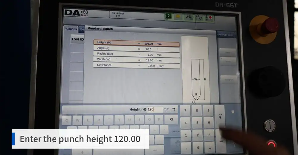
If this is correctly entered, the system can include this information into its logic for setup, enabling it to position the tooling record.
5. Measure And Enter Slot Angle And Radius
To calculate this, the angle of the punch and the radius need to be measured as well. Dans cet exemple:
• Slot angle: 85°
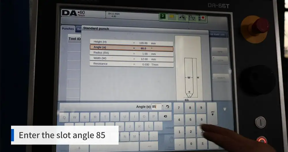
• Radius: 0.5 mm
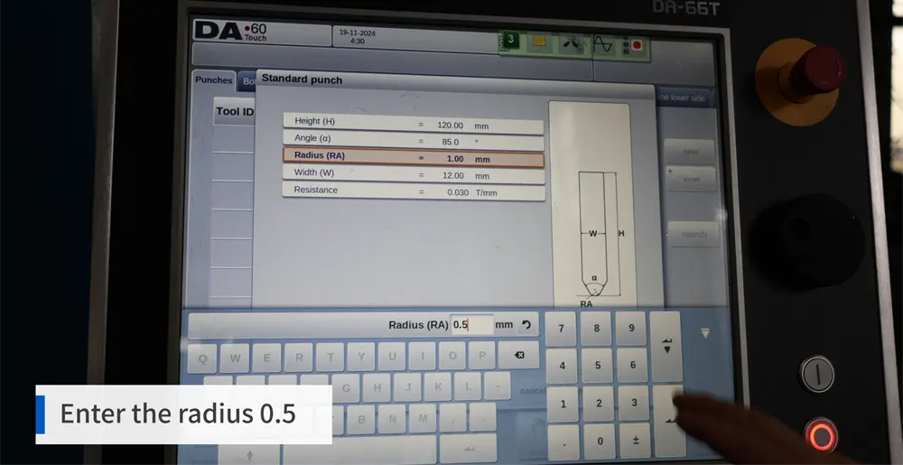
If one of these values is incorrect, then the control will not have the correct punching geometry, and the programmed bending will not be the same as the actual bend that will be on the part.
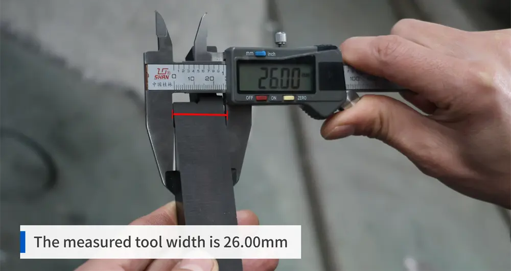
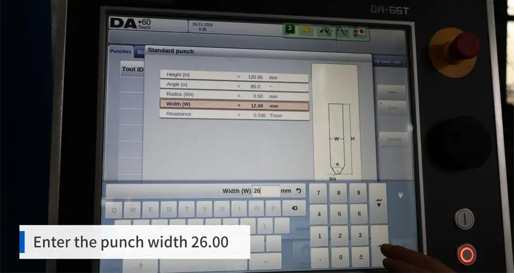
6. Recording Punch Width
Dans ce cas, the punch width is 26.00 mm.
Input this data into the controller. Since width is a component of the complete punch profile, it must always be based on the actual measurement.
7. Punch Resistance Settings
Tiens, the punch resistance value is set to 8.
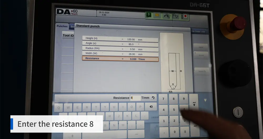
This field is designed to accommodate the tooling data structure established by the system. While varying operations tend to characterize this parameter differently, the key is to ensure uniformity across the tool database.
8. Confirm and Save
Before proceeding, ensure that you have accurately recorded the punch data. Confirm the name, Taille, angle, Rayon, Largeur, and resistance. After reviewing and confirming all entries, finalize the setup and save it. The punch will then be available in the tooling library for upcoming programs.
Pas 2: Completing Tool Setup
With the punch added, your next step is to finish the profile drawing and make any necessary geometric adjustments.
1. Measure All Lengths
Take each profile length measurement needed for the drawing. While using precise values will allow the controller to accurately represent the tool and ultimately improve the quality of the setup, less than accurate values will have the opposite effect.
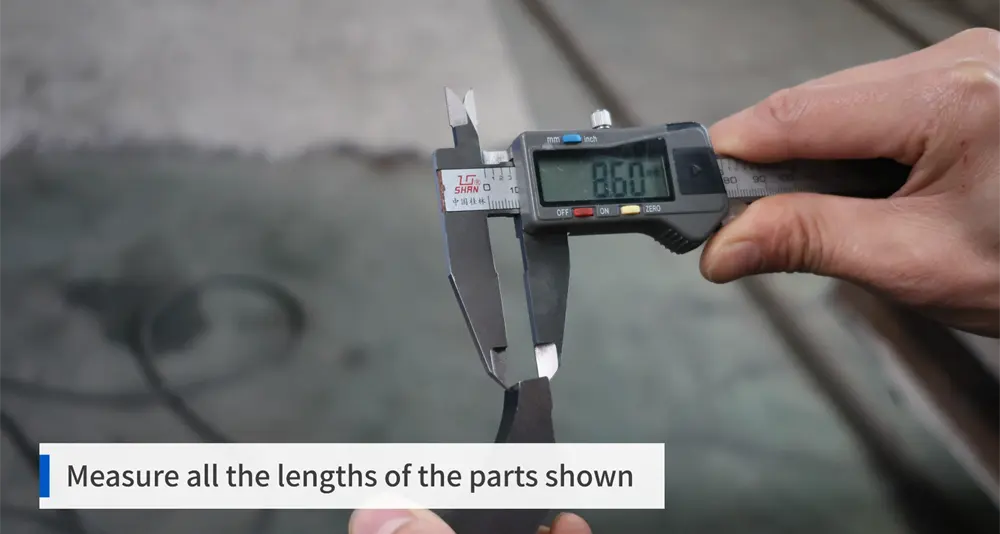
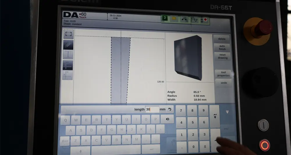
For this example, the lengths measured are:
•8.6 mm
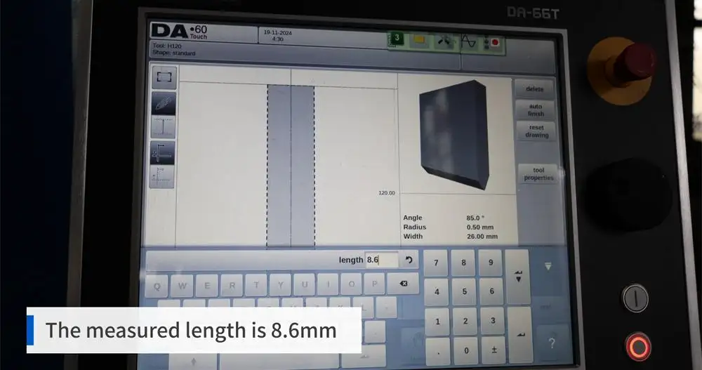
•30 mm
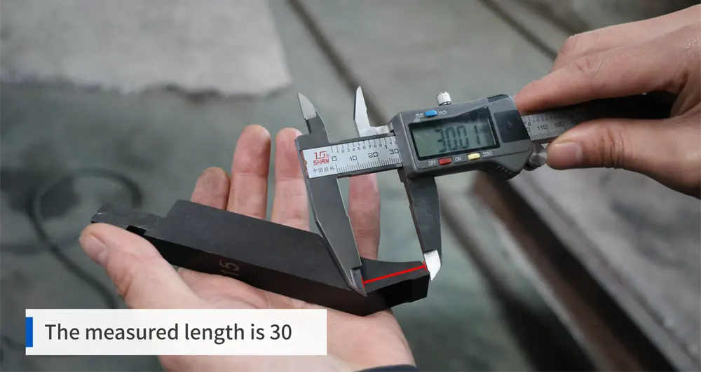
•46 mm
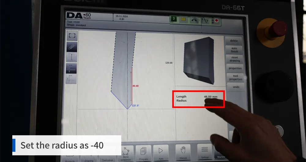
These measurements should be taken directly from the tool.
2. Begin Tool Drawing
Using the measured lengths, draw the tool profile within the controller. This enables the system the geometric information of the punch needed to make the representation complete.
The drawing needs to be simple, clean, et précis. Each point needs to represent the actual profile, not something approximate.
3. Select Radius
Now, enter the radius that you want to use for your drawing. In the image it is shown as -40 mm.
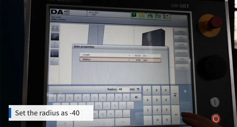
Considering the impact this value would have on the profile being defined, it is advisable to enter it, confirm, and then proceed.
Because of the impact that adjustments to the radius have on the profile, this value is a critical determinant.
If the value is not correctly inputted, the representation of the tools being modeled may not correspond to the real tools.
4. Save and Finish Drawing
Once you have completed the drawing, use the controller to execute a finishing action such as Auto Finish to complete the tool profile and then remember to save.
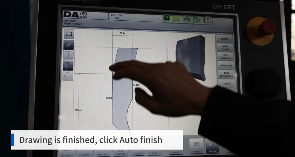
You should have a completed tool geometry on the controller, which should also be useful for future checks and for reusing the tooling record.
5. Clear Unneeded Points
Before confirming, do not forget to clear any unnecessary points or segments from the drawing. Having too many points can make a profile look overly busy and will make future editing more difficult.
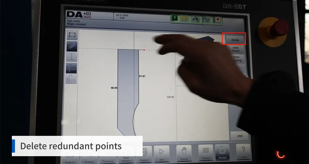
A cluttered profile is harder to verify, more difficult to manipulate, and is ultimately, less desirable for a tooling organization system.
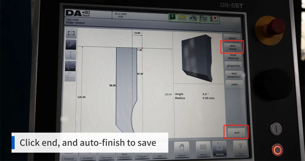
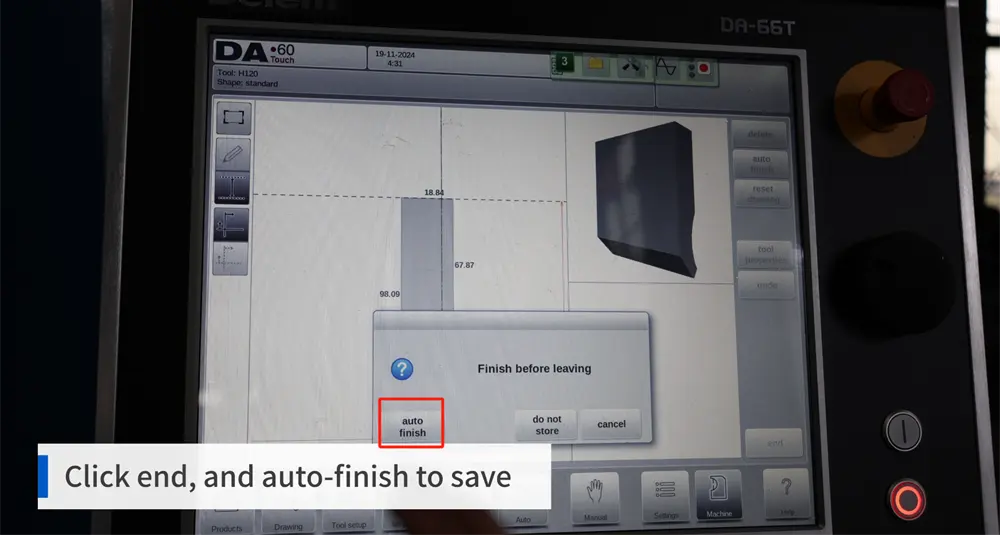
Now that this is complete, the setup for the punch is stored in the system.
Pas 3: Add the Die (Lower Mold)
The last step is to input the lower tool, or die. The die is equally as important as the punch, as it will influence the bend angle, Largeur d’ouverture, and the response of the material during the forming process.
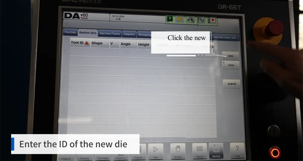
1. Choose 'Add New' For Dies
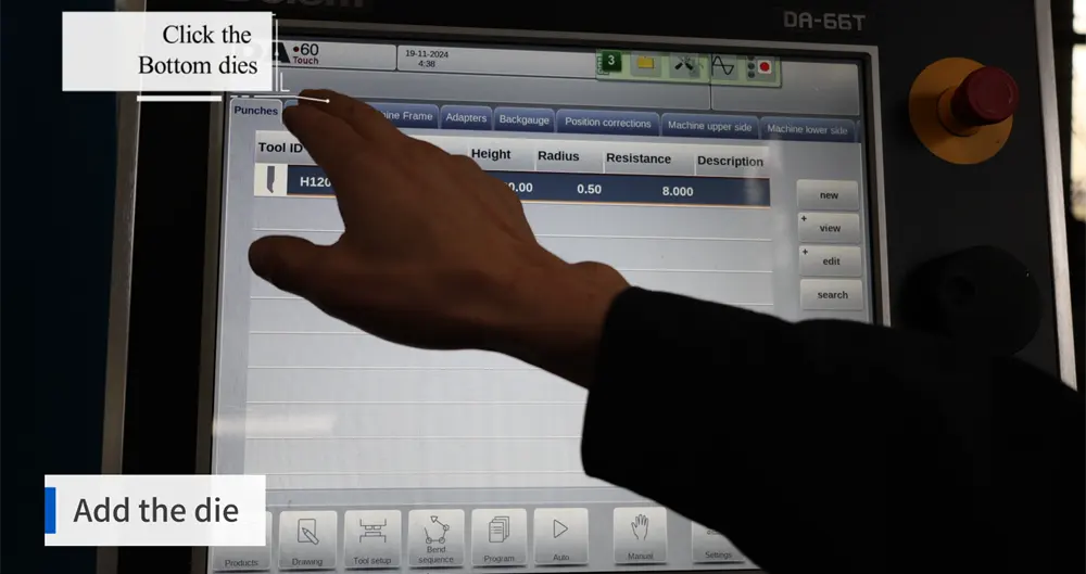
In the die setup section of the controller, you can create a new record for a die. This will take you to a new entry page for the lower mold data.
As for the punch, starting with a new and clearly defined tool file is also a good idea.
2. Input Die Name
Assign the die an appropriate ID or name. The naming convention should be the same as the punch library, so it is easy for the operators to identify the right tool for them during the setup.
3. Die Size
Carefully take the measurements for the die. Exemple:
• Die width: 60 mm
• Die height: 60 mm
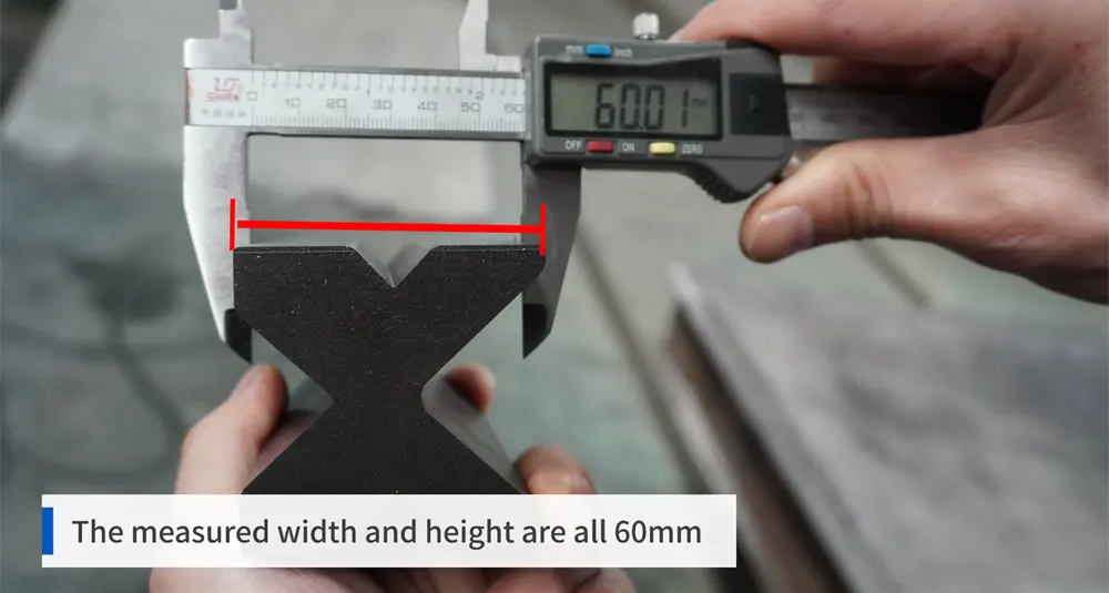
This will form the basic body measurements of the die record.
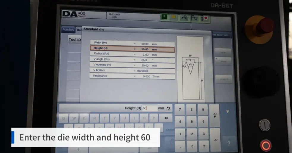
4. Enter The Die Size
Make sure to enter both 60 mm values in the controller. This is how the system will store the actual die size so it can be used in the tooling calculation and display.
5. Enter The Slot Angle And Radius
Now enter the die angle and radius. Par exemple:
• Slot angle: 86°
• Radius: 0.5 mm
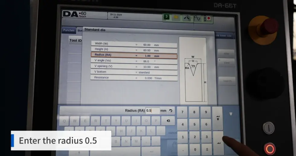
These values should match the actual tool in use, as with the data for the punch.
6. Slot Width Measurement And Entry
The die slot width is 16 mm. Measure that, and enter the value to the system.
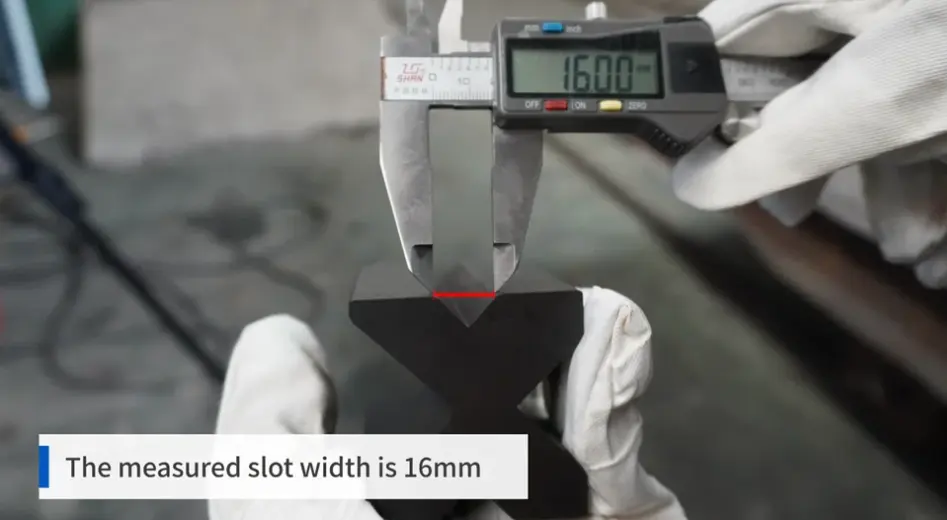
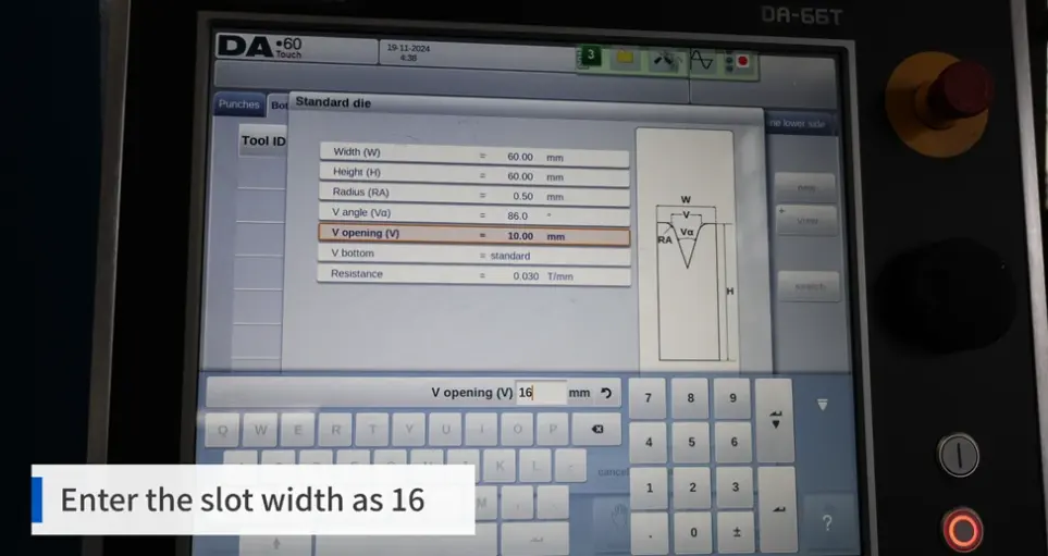
Because the width of the die opening is directly related to the bending behavior and the quality of the part, this is a vital field to fill.
7. Die Resistance Entry
Record the value of die resistance. In this instance, it is also 8.
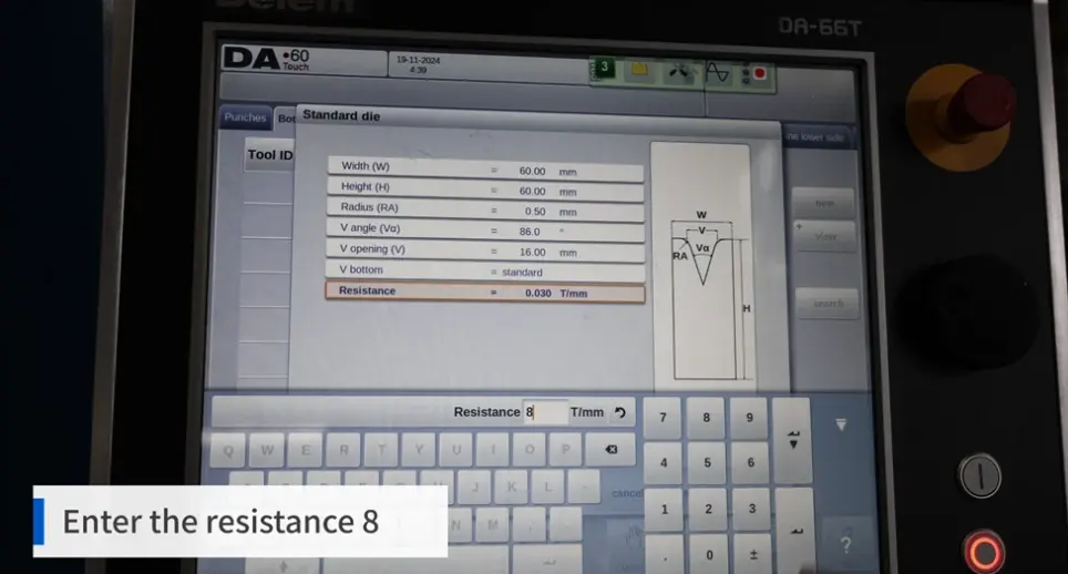
Applying the correct value helps ensure the tooling file remains complete and matches the workshop's tooling data practices.
8. Save And Finalize
Be sure to verify the complete die entry before finalizing and saving it. When the dimensions, angle, Rayon, slot width, and resistance are correct, save the die profile.
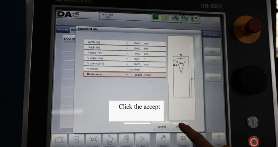
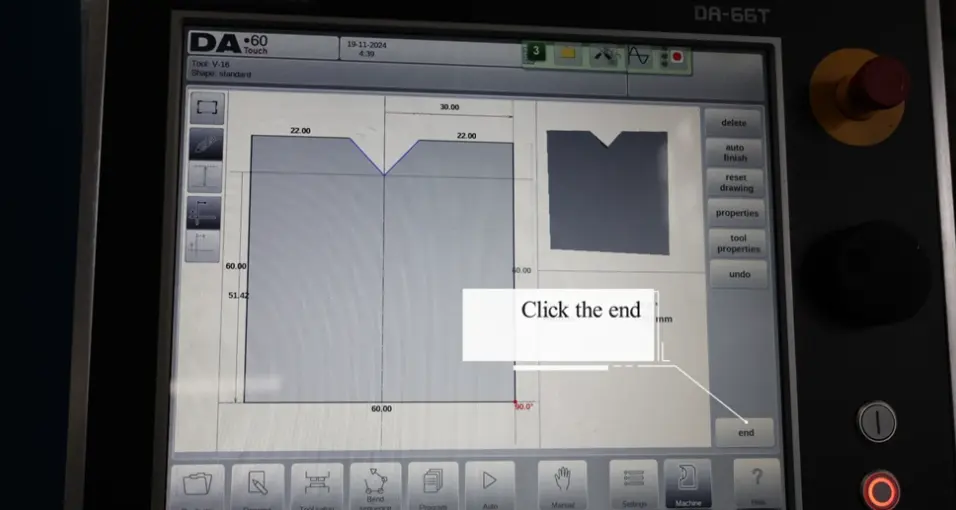
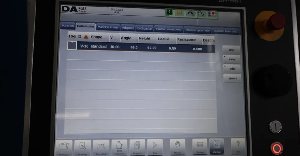
À ce stade, the lower tool will be in the controller and can be programmed or put into production.
Conclusion
By following this process, operators can build a more accurate tooling library inside a Press Brake Delem Controller and make daily setup work more reliable. The key is not speed at the beginning. The key is correct measurement, correct entry, and a clean final review.
Pour JS RAGOS, stable bending starts long before the ram moves. It starts with how punches and dies are defined in the control. When tooling data is entered properly, the machine becomes easier to program, Plus facile à répéter, and easier to trust in production.