


Press Brake Dies and Punches: The Ultimate Selection Guide for Modern Metal Fabrication
By Author: Mark Hanks
Introduction
Press brake dies and punches are far more than minor accessories in metal forming—they are the only components that actually touch your workpiece, making them critical to bending success. While modern press brakes have evolved into multi-axis, high-precision machines with self-stabilizing features, your tooling ultimately determines part quality, setup efficiency, and repeatability.
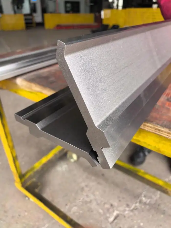
Today, the lines between RFA, New Standard, European, and American standard tooling have blurred. High-performance bending features have migrated across all tool types. Regardless of which style you choose, every quality toolset must meet several non-negotiable requirements.
6 Requirements for Quality Tooling
1. High Precision
Tooling quality demands a tolerance of 0.0004 inches. Being that precise means you can eliminate shimming/adjusting during the setup process. As a result, each part can be produced accurately.
2. Segmented Sections
Pre-cut pieces allow you to build various lengths safely. Smaller segments are easier to handle and significantly safer than long, heavy tools.
3. Self-Retaining Installation
You should be able to load tools with the ram up. The toolholding system must hold multiple pieces in place until clamping pressure is applied.
4. Self-Seating Design
As clamping pressure engages, punches should mechanically pull up into position. This eliminates the need to bottom the punch into the die during setup.
5. Front Loading Capability
Installing tools from the front of the machine dramatically shortens setup time. You no longer need to slide tools from the end of the press brake, and in most cases, front loading eliminates forklifts and overhead cranes.
6. Standard Heights
Common-height tools reduce machine adjustments when changing jobs. Front support arms, backgauge heights, and safety devices remain at consistent positions. Plus, you can add off-the-shelf pieces that match your existing tools.
✅ Note: Many high-quality press brake tools follow metric standards. For air bending (the focus of this guide), imperial dimensions are rounded for simplicity.
Evaluate Your Requirements First
A custom shop will need entirely different tools to maintain than a custom fabricator. You must first evaluate:
• Types and quantities of parts
• Thickness of materials
• Financial restrictions
• Goals for lean manufacturing
As a suggestion, you should make tool libraries for every press brake. When a tool set remains at a machine, there is no time wasted walking back and forth to get tools. Also, if tools are set at each press brake, the tools no longer need to be compatible to different machines.Look for tools with the most wear—shiny, bright working surfaces indicate frequently used, reliable options. Rusty, dirty tools at the bottom of the rack are rarely good candidates.
Die Selection: The 8×2 Rule
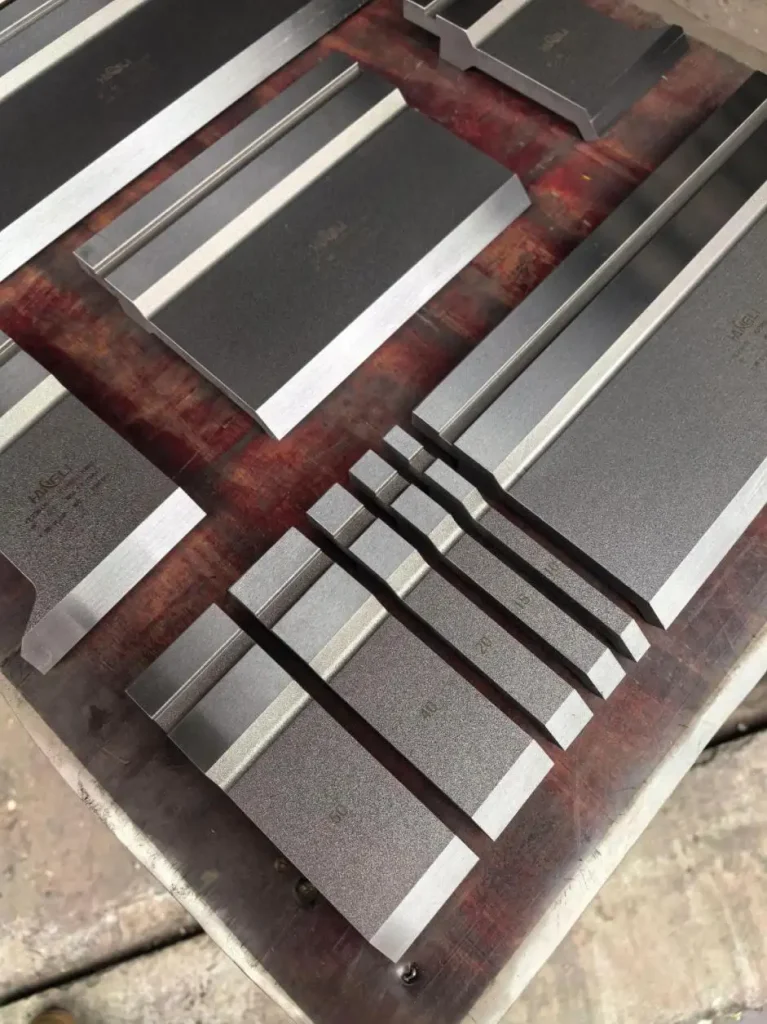
To maximize value, choose a minimum number of lower dies that cover your entire material thickness range.
Step-by-step example (for materials 0.030 to 0.250 inches thick):
| Step | Calculation | Result |
| Smallest V die | 0.030 × 8 = 0.24 | Round to 0.25 inches |
| Largest V die | 0.250 × 8 = 2.0 | 2.0 inches |
| Fill the gap | Double each size | 0.5, 1.0 inches |
Your minimum set: 0.25, 0.5, 1.0, and 2.0-inch V dies
Punch Selection by Material Thickness
| Material Thickness | Recommended Punch Type | Tip Radius |
| Up to 0.187 inches | Acute offset knife punch | 0.04 inches |
| 0.187 to 0.5 inches | Straight punch | ~0.120 inches |
| Above 0.5 inches | Consult material supplier | Varies |
The acute offset punch allows bending past 90 degrees and forming J shapes. For thicker or high-tensile materials, a narrow punch tip combined with a narrow V-die opening can cause creasing or cracking—always verify recommendations for challenging applications.
The Rule of 8: Your Bending Sweet Spot
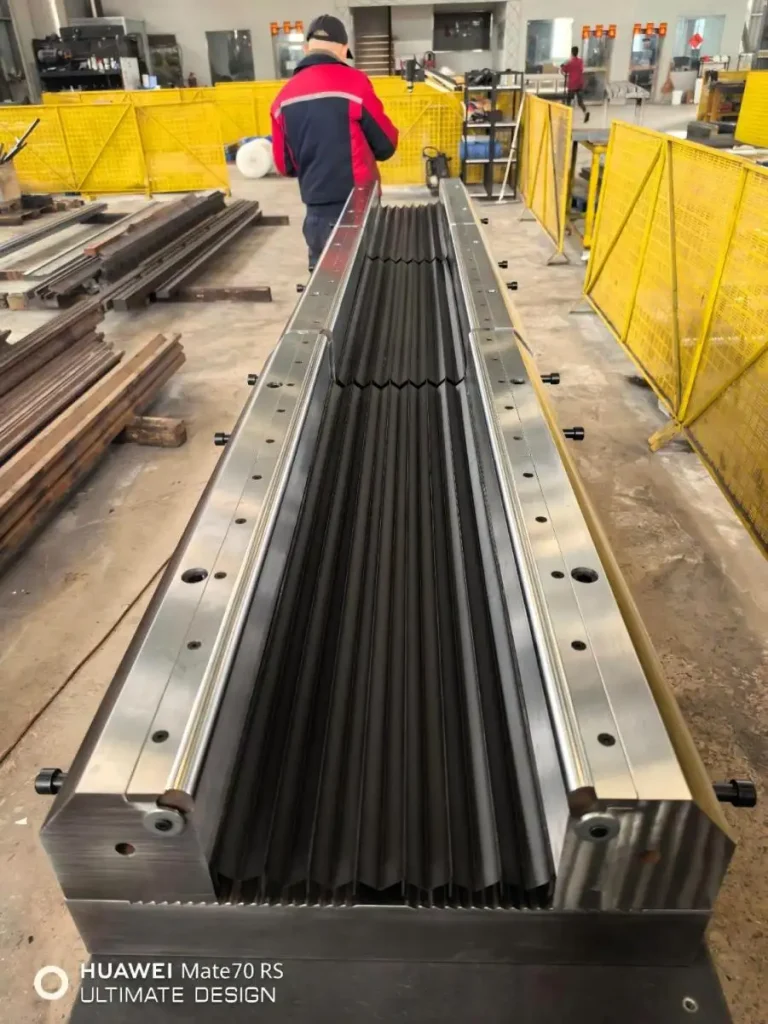
In ideal conditions, the V-die opening should be 8 times the material thickness.
| Material Thickness | Calculation | Recommended V Die |
| 0.060 inches | 0.060 × 8 = 0.48 | 0.5 inches |
| 0.125 inches | 0.125 × 8 = 1.0 | 1.0 inches |
This ratio delivers the best angular performance—which is why most published bending charts center on this formula.
Real-world exception: When designers specify bend radii different from the rule of 8, you'll need to adjust.
How V-Die Opening Determines Bend Radius
When air bending mild steel, the inside bend radius equals approximately 16% of the V-die opening.
| Desired Inside Radius | Material Thickness | Calculation | Recommended V Die |
| 0.125 inches | 0.125 inches | 0.125 ÷ 0.16 = 0.78 | 0.75 inches |
| 0.320 inches | 0.125 inches | 0.320 ÷ 0.16 = 2.0 | 2.0 inches |
Warning: If you need a V-die opening less than 5 times the material thickness, you risk:
• Compromised angular accuracy
• Machine and tooling damage
• Unsafe operating conditions
Minimum Flange Length Requirements
A V die can form flanges nearly 77% of its opening.
| V Die Size | Minimum Flange |
| 1.0 inches | 0.77 inches |
| 0.625 inches | 0.48 inches (~0.5) |
✅ Example: A drawing shows 0.125-inch material with a 0.5-inch flange. The 8:1 rule requires a 1-inch V die, but this gives a 0.77-inch flange. What to do? Use a 0.625-inch V die.
Again, never go below 5× material thickness for die width.
Punch Selection Rules by Shape
L Shapes: No Rules
Almost any punch shape works. Select punches that can also handle other part shapes—less is always best for minimizing both tooling cost and setup time.
J Shapes: Three Rules
| Condition | Required Punch |
| Condition 1 (Up-leg > Bottom-leg / Flange is shallow) | Standard straight or acute punches |
| Condition 2 (Up-leg < Bottom-leg / Inward deep return) | Gooseneck punch |
| Small up-leg = bottom leg | Offset acute punch |
Offset (Z) Shapes
With conventional tools, you need two ram cycles. Requirements:
• Center leg (web) > half the V-die body width
• Side leg < V-die height + riser height
✅ Special case: When the web is less than half the V-die body width, you need a custom form tool (one stroke, no plate flipping). Trade-off: This is a coining process that requires up to 5× to 6x standard air-bending tonnage.
Bending Across Cutouts and Miters
Unsupported material inside the V die deforms, creating "blowouts" near holes and cutouts.
• Solution: Rocker-type dies eliminate blowouts identically, as they support the material while bending and rotate with the work operand piece.
• Key insight: Longer cutouts produce more blowout than shorter ones of the same width.
Punch Height for Box Bending
For four-sided boxes, use this formula:
Minimum punch height = (Box depth ÷ 0.7) + (Ram thickness ÷ 2)
Additional considerations:
• No return flanges or outward-protruding flanges = minimal clearance needed
• Return flanges on all four sides = enough clearance to twist and remove the box
Combination Bend and Hem Tools
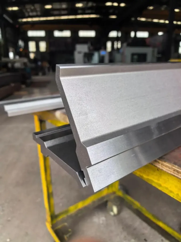
These tools form hemmed edges in a single setup.
| Material Thickness | Feasibility |
| Up to 0.125 inches | Standard tools work |
| Above 0.125 inches | May require custom tools |
Flange requirement for hems: Minimum 150% to 200% of the V-die opening width (due to the deeper penetration required during the preliminary 30° acute pre-bend).
✅ Example: A V10 die requires an 15.0 mm to 20.0 mm minimum flange before hemming.
Achieving Scratch-Free Parts
Standard V-die bending leaves some marks—usually minimal and acceptable. To reduce marking:
• Increase the shoulder radius
• Use nylon inserts for prepainted or polished materials
�� Critical applications: Aircraft/aerospace parts require scratch-free bending because inspectors cannot easily distinguish between scratches and cracks.
Simplicity Is a Virtue: 3 Rules for Part Design
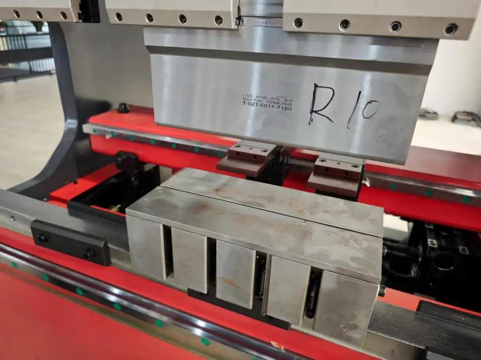
Consider these rules when designing parts for simpler tool selection and bending:
| Rule | Specification |
| Inside Bend Radius | 1.5× Material Thickness |
| Minimum Flange Length | 6× Material Thickness (with hole placement) |
| Offset Web Dimension | 10× Material Thickness |
Every exception comes with its own problems:
• Tighter radii can crease and exceed tonnage
• Shorter flanges need narrower dies (with their own risks)
• Narrower offsets need special tools and increased tonnage
In general, if a part can function without short flanges, narrow offsets, or tight radii, find a way to avoid using them. Follow these rules for better angular performance while decreasing the time and money spent on tools and setups.
Final Takeaways
| Priority | Action Item |
| Start here | Assess your material range and part types |
| Invest wisely | Buy precision tools meeting all 6 requirements |
| Simplify | Use the 8×2 rule for dies and material-based punch selection |
| Design smart | Follow the 3 part-design rules |
| When in doubt | Consult your tooling supplier—especially for challenging applications |
Press brake dies and punches are your most direct influence on bending quality, speed, and safety. Choose them wisely, maintain them properly, and your press brake operation will deliver consistent, high-quality results—setup after setup.