
Sheet Metal Bending Interference: Causes & Solutions
Bending interference is a common issue in multi-step sheet metal operations. Interference occurs when the workpiece, tooling, or machine collide during the bending operation. Here at JS RAGOS, we work to define and eliminate we help with tailored tooling, process, and design solutions. This guide offers insight into possible interferences and offers solutions from our experiences on-site.
1. Why Bending Interference is Important
Bending is the most important operation in sheet metal. This operation relies on the plastic deformation of the metal to create parts of a specific geometry and dimensions. When compared with the processes of welding, riveting, or bolting, the process of bending has the following benefits.
• Greater precision and repeatability
• Reduced tooling and labor expenses
• Shorter cycle time
• Improved appearance by eliminating joints and seams
However, the use of more complex geometries creates a greater chance of bending interference. Without appropriate planning of the process, the selection of the right tools and the consideration of the right order of operations, bending interferences can make the fabrication of a part impossible. At JS RAGOS, we start addressing issues of interference at the design phase of the part to ensure efficient, seamless fabrication.
2. What is Sheet Metal Bending Interference?
Bending interference occurs mostly on components that have been designed to undergo two or more bends. In such cases, the interference occurs due to a physical collision between a bent edge of a component in the process and the die, the punch, the machine frame or a feature of the component. The main influencing factors are:
• Part shape and dimensions
• Tooling (punch & die)
• Machine structure (bed width, ram stroke, back gauge travel)
• Bending sequence
Below are the three most common types of bending interference, illustrated with typical examples.
2.1 Interference Between Bent Edge and Tooling
This is the most frequent interference type. During the bending rotation, the already-bent edge hits the punch (upper die) or the die (lower die), causing deformation or halting the process.
• Upper die interference – The bent edge strikes the punch as it rotates upward.
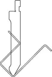
Figure 1: Upper mold interference
• Lower die interference – The part collides with the die shoulder or the lower tool.
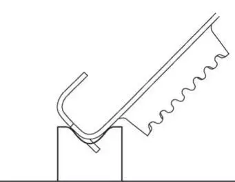
Figure 2: Lower die interference
�� Example: A tall flange on a “U”-shaped part can easily hit the punch. JS RAGOS recommends checking tool clearance early in the design phase.
2.2 Interference Between Part and Machine
This occurs with enclosed or oversized geometries, such as:
• Three-sided closed bends – After bending two parallel sides, the high vertical walls hit the upper die when attempting the third side. Also, the machine bed or back gauge may block part positioning.
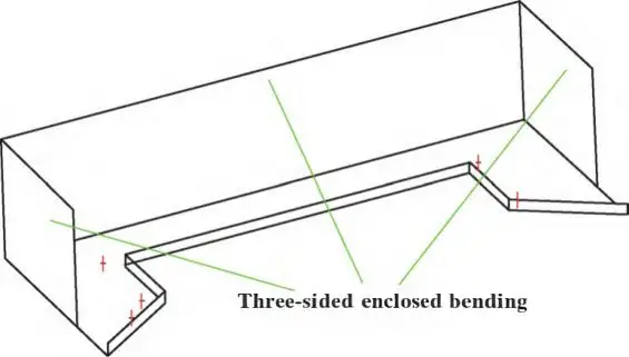
Figure 3: Three-sided enclosed bending
• “Z”-shaped bends – A simple offset (Z-bend) often fails: after the first 90° bend, the long leg points downward and strikes the machine table during the second bend.
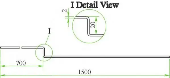
Figure 4: Z-shaped bending
✨ JS RAGOS insight: Many so-called “unbendable” parts can be saved by adjusting the bending order or using special tooling — see Section 3.
2.3 Interference with Other Part Features
In parts with tight assembly requirements, accumulated tolerances and springback can cause edges to collide or angles to fall short.
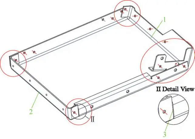
Figure 5: Bending with an assembly structure
�� Example: A box-like part with internal mating flanges. If the width tolerance is too negative (over-bent), the side flanges crash into each other. Without a proper gap at certain positions, the bend angle cannot reach 90°.
These cases demand a holistic approach: tolerance analysis, springback compensation, and sequence planning.
3. Practical Solutions to Sheet Metal Bending Interference
Based on decades of manufacturing experience, JS RAGOS applies the following strategies — often in combination — to solve interference problems efficiently.
3.1 Optimize Tooling Selection & Modify Die Shapes
Choice of tooling is the first line of defense.
• Hooked / gooseneck punch – The most common solution for “U”-shaped parts. Its recessed design provides clearance for tall flanges. JS RAGOS offers a range of gooseneck punches and can recommend the right size based on your flange height and bottom width.
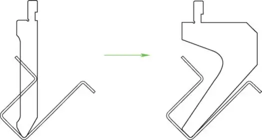
Figure 6 Bend Hook Die
• Modified standard tooling – Notch, mill, or drill clearance holes in the punch or die where interference occurs. However, always verify that the remaining tool body has sufficient strength to avoid premature wear or deflection.
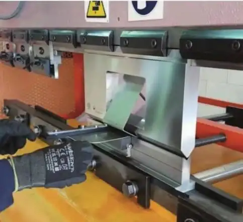
Figure 7: Modified Mold
When even a gooseneck punch cannot clear the part, JS RAGOS recommends a score line or V-groove bending (also called “routing before bending”).
Score line / V-groove method:
• Press a shallow indentation (or mill a V-groove, depth ≈ 80% of sheet thickness) along the bend line.
• The groove allows partial pre-bending (e.g., to 135° instead of 90°), avoiding tool collision in subsequent steps.
• Finally, flatten to 90°.
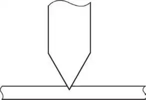
Figure 8: Wire Pressing Process
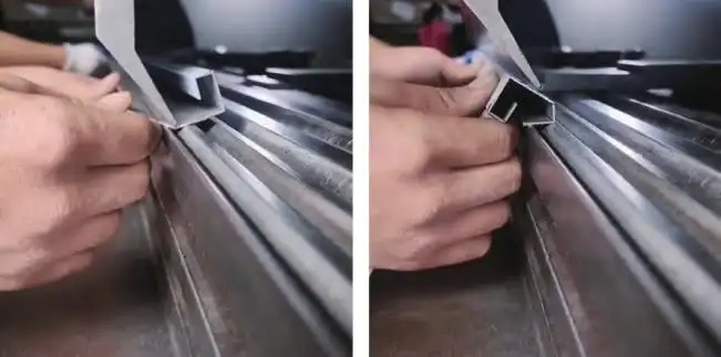
a) Grooving and pre-bending b) Grooving, bending, and correction
Figure 9: Grooving and Bending
�� Caution: Deep grooves can reduce strength or cause cracking — evaluate per application. JS RAGOS can run feasibility tests for your specific material and thickness.
3.2 Design a Smart Bending Sequence
A clever sequence often eliminates the need for complex tooling.
For the Z-bend example:
Instead of bending both legs to 90° directly:
• Pre-bend the first leg to about 135°.
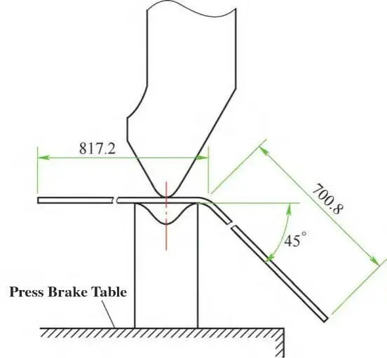
Figure 10: Schematic of pre-bending
• Bend the second leg fully to 90°.
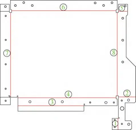
Figure 11: Bending Sequence
• Return to the first leg and finish it to 90°.
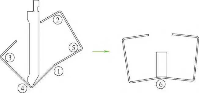
Figure 12: Process of pre-bending
For complex, multi-bend parts:
• Use reverse-order reasoning – determine the last bend first, then work backward. This ensures that critical flanges (which are hardest to access) are bent last, avoiding interference with the punch.
Pre-bending as a sacrificial operation:
Add a temporary reverse bend (small angle) where interference is predicted. After completing the main bends, the temporary bend is either corrected or removed.
JS RAGOS helps customers simulate bending sequences using CAD/CAM and field-tested knowledge — saving weeks of trial-and-error.
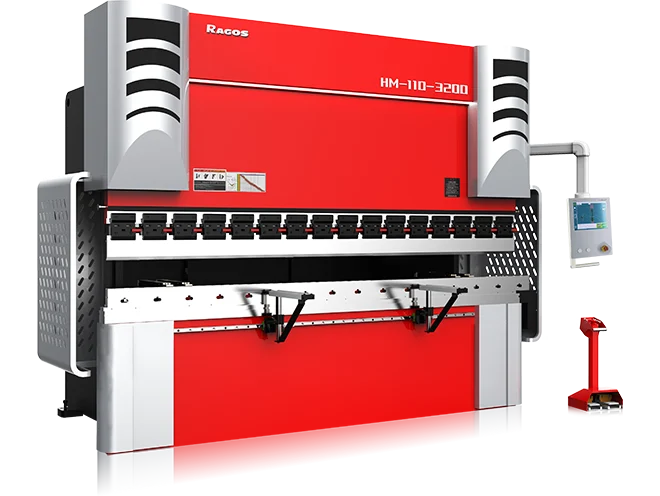
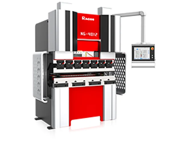
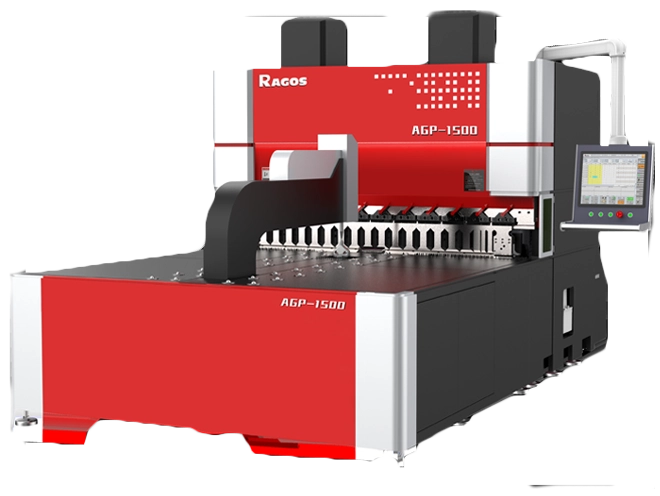
3.3 Choose the Right Bending Equipment
Not all press brakes are equal. Two main types:
• Up-forming (bottom-ram) presses – Suitable for thin sheets; the punch moves upward from below.
• Down-forming (top-ram) presses – The punch moves downward; better for thick plates and large workpieces.
Main machine parameters influencing interference:
• Open height & stroke – Inadequate space for extended clearance on tall flanges.
• Bed width – Wide beds can block parts that extend below the die.
• Back gauge travel range & layout – May conflict with long or asymmetric parts.
JS RAGOS operates a range of modern CNC press brakes (including models with advanced interference-avoidance software) and can advise on machine selection for your specific part family.
3.4 Design Custom / Non-Standard Tooling
For highly complex geometries, off-the-shelf tooling will not suffice. JS RAGOS designs and manufactures dedicated non-standard bending tools, including:
• Single-piece shaped dies (e.g., stepped punches, radius-tailored forms)
• Modular assemblies (multi-component moving tools that “expand” or “collapse” during stroke)
Custom tooling requires careful analysis of part geometry, material, batch size, and cost. JS RAGOS provides end-to-end service: feasibility study → 3D design → in-house production → try-out.
3.5 Improve Part Design for Bendability
Sometimes the best solution is to modify the product design without affecting its function or dimensions.
Real case from JS RAGOS (locomotive lamp cover):
The original design had two acute-angle flanges and a separate weld seam. After analysis, we swapped the weld seam and one flange:
• The previously acute flange became a straight bend (easy to form).
• The original flange became a weld seam (shortened by 45%).
Results:
• No bending interference.
• 55% reduction in weld length → lower cost, higher throughput.
• No special tooling required.
JS RAGOS offers DFM (Design for Manufacturability) reviews at the early prototyping stage to catch such opportunities.
4. Summary & Why Choose JS RAGOS
Sheet metal bending interference is inevitable as parts grow more complex, but it is never unsolvable. The key is to combine:
• Proper tool selection (standard, modified, or custom)
• A well-planned bending sequence (pre-bends, reverse logic)
• Awareness of machine limitations (and choosing the right equipment)
• Design optimization (changing features that cause self-interference)
As a dedicated manufacturer, JS RAGOS does not just write about solutions — we apply them daily on our shop floor. Whether you need gooseneck punches, V-groove bending, process simulation, or fully custom tooling, we deliver practical, cost-effective answers to Sheet Metal Bending Interference.
Get in touch with JS RAGOS for a free DFM analysis of your most challenging bending parts. Let’s bend smarter, not harder.