


Hydraulic Press Brake Troubleshooting: Common Faults & Fixes
Technically reviewed by [Mark Hanks], Chief Engineer at JS RAGOS
A hydraulic press brake relies on its hydraulic system to provide stable pressure, controlled operating speed, and precise ram position control. Abnormal conditions involving the hydraulic oil, valve manifold, hydraulic pump, seals, or pressure-holding circuit may cause problems such as unintended ram drift, insufficient bending force, irregular operating speeds, excessive oil temperature, or reduced bending consistency.
Troubleshooting should not begin by immediately replacing the hydraulic pump or valve manifold. A more reliable approach is to first document the symptoms and alarm messages, then inspect the safety interlocks, hydraulic oil condition, external leakage, system pressure, ram movement, and critical hydraulic components in a logical sequence. This systematic process helps isolate the fault while minimizing unnecessary downtime and component replacement.
Based on the hydraulic circuit and field service cases of the JS RAGOS HG-250T-3200 mm Hydraulic Press Brake, this article outlines the recommended diagnostic sequence, probable causes, and corrective actions for common hydraulic faults. Any pressure, temperature, or solenoid valve actuation parameters mentioned should be published only after an engineer has verified them against the technical manual for this specific machine model. They should not be treated as universal settings for all hydraulic press brakes.
1.Common Hydraulic Press Brake Problems: Quick Overview
Hydraulic press brakes operate under continuous high pressure, so oil condition, component wear, and temperature changes can gradually affect machine performance.
Common symptoms include ram drift, low or unstable pressure, overheating, oil contamination, leakage, abnormal noise, and inconsistent bending results.
Use Table 1 as a quick fault index. Confirm the symptom first, then follow the diagnostic sequence in Section 2 before replacing components.
Table 1 — Common Hydraulic Press Brake Problems, Causes, and First Actions
| Hydraulic Press Brake Symptom | Possible Cause | Recommended First Action |
| Unexpected ram drift or slipping | Cylinder internal leakage; pilot-operated check valve failure | Stop the machine, isolate stored energy, and inspect the cylinder seals and holding-valve circuit |
| Unstable hydraulic pressure | Hydraulic pump wear; directional valve wear; incorrect pressure adjustment | Measure pressure at the specified test points; inspect the relief valve, directional valve, and pump output |
| Hydraulic oil overheating | Excessive operating temperature; insufficient cooling | Check the oil level, cooler airflow, oil viscosity, and operating duty cycle |
| Hydraulic system contamination | Dirty oil; metal particles; improper filtration | Filter or replace the oil as specified; clean the reservoir and replace the filters |
2. How to Troubleshoot a Hydraulic Press Brake
Safety Notice: Before beginning any inspection, follow the lockout/tagout (LOTO) procedures specified by your company and the machine manufacturer. Disconnect and isolate all electrical, hydraulic, and other energy sources; relieve or securely control any residual pressure; and use manufacturer-approved mechanical supports to prevent unintended ram movement. Pressure testing, valve manifold disassembly, hydraulic cylinder repair, and parameter adjustment must be performed only by trained and authorized technicians.
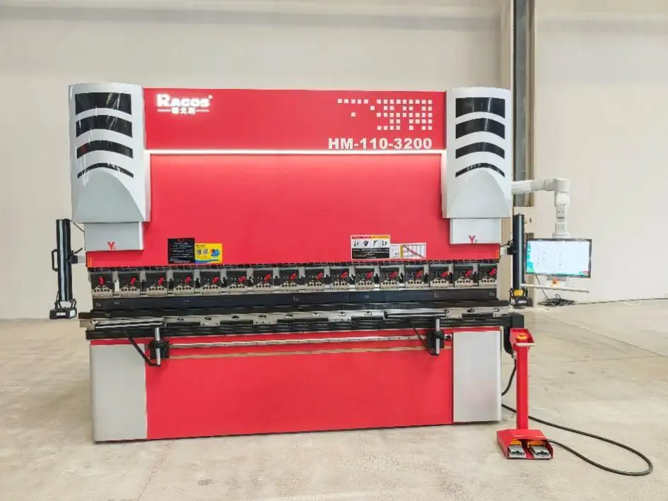
When a hydraulic press brake operates abnormally—for example, when the ram cannot hold its position, bending pressure is insufficient, forming accuracy decreases, or operating speed becomes irregular—components should not be replaced immediately. Effective troubleshooting should follow the hydraulic system's operating sequence, progressing systematically from observable symptoms to critical hydraulic components.
Before classifying the problem as a hydraulic fault, inspect the emergency-stop circuit, safety doors or light curtains, foot switch, controller alarms, limit-switch signals, and solenoid valve coil commands. Electrical interlock or control-signal faults can produce symptoms similar to hydraulic pressure loss or failure of the ram to move.
2.1 Step 1: Check Hydraulic Oil Condition and Temperature
Hydraulic oil is not only the medium that transmits power through the hydraulic system; it also directly affects the performance of the hydraulic pump, control valves, seals, and other components. Before inspecting more complex hydraulic components, verify that the hydraulic oil is in serviceable condition.
Key inspection points include:
• Check whether the hydraulic oil level is within the specified range.
• Inspect the oil for discoloration, cloudiness, or visible contamination.
• Check for metallic particles, foreign matter, or water contamination.
• Confirm whether the hydraulic oil has been inspected and replaced according to the prescribed maintenance schedule.
• Verify that the operating oil temperature remains within the range specified by the manufacturer.
Contaminated hydraulic oil may cause valve-spool sticking, accelerate hydraulic pump wear, and reduce system pressure. Excessive oil temperature can lower viscosity and lubrication performance, accelerate seal deterioration, and shorten the service life of hydraulic components.
2.2 Step 2: Check Hydraulic Pressure Stability
After confirming that the hydraulic oil is in acceptable condition, determine whether the system can maintain stable pressure throughout the operating cycle.
Unstable hydraulic pressure may cause:
• Noticeable pressure fluctuations during bending
• Variations in bend angle or finished-part dimensions
• Reduced repeatability between workpieces
• Abnormal or inconsistent ram movement
These symptoms may indicate that the fault has progressed beyond basic oil-condition issues and is associated with the pressure-holding or pressure-control circuit.
At this stage, verify whether:
• The system can build and maintain the required pressure.
• The hydraulic lines, fittings, and cylinders show any visible leakage.
• The pressure-control components and settings are functioning correctly.
2.3 Step 3: Inspect the Hydraulic Cylinders and Ram Movement
If the press brake exhibits unintended ram drift, the ram-holding circuit may not be functioning correctly.
Key inspection points include:
• Check the hydraulic cylinder seals for wear or damage.
• Determine whether internal leakage or piston-seal bypass is occurring inside the cylinders.
• Verify that the pilot-operated check valve can close correctly and hold pressure.
Under normal conditions, the hydraulic cylinders, pilot-operated check valve, and pressure-holding circuit work together to maintain a stable ram position. A failure in any of these components may allow the ram to descend slowly.
2.4 Step 4: Inspect the Hydraulic Valves and Pump
If the hydraulic oil is in good condition and no obvious cylinder leakage or ram-holding fault has been identified, but system pressure remains unstable, inspect the hydraulic pump, valve manifold, and related pressure-control components.
Hydraulic Pump Checks
Pump wear can reduce volumetric efficiency, making it difficult for the hydraulic system to build or maintain the required operating pressure. Check the pump for signs of abnormal wear, excessive internal leakage, unusual noise, or declining output performance.
Hydraulic Valve Checks
Hydraulic valves control oil-flow direction, pressure, and actuator movement. Wear or damage to a valve spool or valve seat may result in:
• Increased internal leakage
• Reduced or unstable system pressure
• Irregular spool movement or spool sticking
Particular attention should be given to the electro-hydraulic directional control valve, as spool wear, contamination, or sticking may disrupt normal oil flow and pressure stability.
If the preliminary inspections reveal no obvious cause, the hydraulic pump, directional control valves, and associated pressure-control components should be tested systematically to identify the source of the pressure abnormality.
3. How the HG-250T-3200mm Hydraulic System Works
3.1 Hydraulic System Operating Principle
In the HG-250T-3200mm configuration shown here, a fixed-displacement piston pump pressurizes the hydraulic oil. Check valves and an electro-hydraulic directional valve then control oil flow to the hydraulic cylinders.
When the directional valve switches to the return position, pressurized oil enters the lower cylinder chambers through the pilot-operated check valves and drives the ram upward.
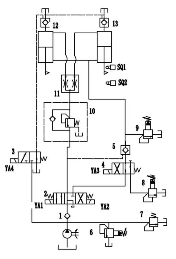
Figure 1 — Hydraulic Schematic Diagram of the HG-250T-3200mm Hydraulic Press Brake
The main solenoid valve operating sequence is shown below.
Table 2 — Solenoid Valve Actuation Sequence
| Action Sequence | YA1 | YA2 | YA3 | YA4 |
| Pump Start | + | - | - | + |
| Ram Fast Down | + | - | + | - |
| Ram Working Feed | + | - | - | - |
| Ram Return | - | + | - | + |
During the downward stroke, solenoids YA1 and YA3 are energized. Hydraulic oil flows through the directional valve, sequence valve, and flow divider into the upper chambers of the cylinders. The ram quickly descends due to hydraulic pressure and gravitational force acting on it.
When the system reaches the working position, it switches to the slow working feed stage. For pressure stabilization, the relief valve adjusts the working pressure due to the closure of the pilot-operated check valve.
During the upward stroke, YA2 is energized and pressurized oil is permitted to the lower chambers of the cylinders, thereby returning the ram to its upper position.
3.2 Hydraulic Circuit Analysis
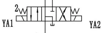
Figure 2 — Main Solenoid Valve Operation Diagram
3.2.1 Downward Stroke
When YA1 is energized, the electro-hydraulic directional valve switches to the downward-stroke position. Pressurized hydraulic oil is directed into the upper chambers of the cylinders, driving the ram downward.
Oil Flow Path
Supply:
Tank → Pump → Electro-hydraulic directional valve → Sequence valve → Flow divider → Upper cylinder chamber
Return:
Lower cylinder chamber → Pilot-operated check valve → Solenoid valve → Directional valve → Tank
3.2.2 Upward Stroke
When YA2 is energized, the directional valve switches to the return position. Pressurized hydraulic oil flows into the lower chambers of the cylinders, driving the ram upward to its return position.
Oil Flow Path
Supply:
Tank → Pump → Directional valve → Pilot-operated check valve → Lower cylinder chamber
Return:
Upper cylinder chamber → Hydraulic return circuit → Tank
1. Field Case Studies: Hydraulic Fault Analysis
The following case studies are based on inspections of a JS RAGOS HG-250T-3200mm hydraulic press brake.
4.1 Unexpected Ram Drift: Causes and Solutions
Unexpected ram drift occurs when the ram cannot hold its commanded position and slowly moves downward while the machine is stopped or holding pressure. This symptom indicates a fault in the hydraulic holding circuit.
Under normal conditions, the cylinders, pilot-operated check valves, and pressure-holding circuit keep the ram in position. Internal cylinder leakage or a faulty holding valve can allow the ram to drift downward.
The main causes are:
- Internal leakage in a hydraulic cylinder
- Failure of a pilot-operated check valve
Fault Analysis
Cause 1: Hydraulic Cylinder Internal Leakage
Failed piston seals can allow oil to bypass internally between the cylinder chambers, reducing holding pressure and causing the ram to drift.
Scoring or wear on the piston rod or cylinder bore may also damage the seals and increase internal leakage.
Inspect the cylinder and replace the seals or repair the cylinder as specified by the manufacturer.
Cause 2: Pilot-Operated Check Valve Failure
If the pilot-operated check valve does not seal correctly, oil can flow backward and the cylinder may be unable to hold the ram in position.
Have an authorized technician inspect and clean the valve. Replace the valve if it cannot be restored within the manufacturer's specifications.
Confirmed Cause and Corrective Action
A portable hydraulic tester indicated that the pilot-operated check valve was functioning normally. Further inspection found severe wear and deformation in the left-cylinder seals.
After the damaged seals were replaced, repeated operating tests showed no further ram drift.
4.2 Unstable Hydraulic Pressure: Causes and Solutions
Stable hydraulic pressure is essential for bending accuracy and repeatability. Pressure fluctuations can cause angle variation, dimensional deviation, and inconsistent results between workpieces.
Unstable hydraulic pressure is usually not caused by a single factor. It may be related to reduced hydraulic pump efficiency, worn hydraulic valves, internal or external leakage in the hydraulic cylinders, or incorrect pressure adjustment. Therefore, when diagnosing this type of fault, each critical component should be inspected step by step according to the operating sequence of the hydraulic system.
Fault Analysis
The causes may be as follows:
- Internal leakage in the hydraulic cylinders
- Hydraulic pump wear and reduced volumetric efficiency
- Incorrect relief-valve pressure adjustment
- Wear in the electro-hydraulic directional valve spool
Test results showed:
- No significant internal leakage was detected in the hydraulic cylinders
- The relief-valve setting matched the specified test condition
The fault was ultimately traced to wear in the directional valve spool.
Confirmed Cause and Corrective Action
The electro-hydraulic directional valve was removed and both the spool and valve seat showed evidence of wear.
This type of wear will result in:
- Increased internal leakage
- Loss of pressure
- Directional valve spool sticking
5. Hydraulic Press Brake Maintenance and Fault Prevention
In addition to repairing faults after they occur, establishing a systematic preventive maintenance program is even more important for improving the long-term reliability of hydraulic press brakes.
Routine maintenance should include checking the hydraulic oil level, monitoring changes in oil color and condition, inspecting hydraulic lines for leakage, verifying that system pressure remains within the normal range, and regularly checking hydraulic valves and seals for wear or deterioration.
For press brakes operating continuously under heavy loads, particularly high-tonnage hydraulic press brakes, proper control of hydraulic oil temperature is especially important. Excessive oil temperature can reduce hydraulic fluid performance, accelerate seal aging, and shorten the service life of hydraulic components.
Three common contributors to hydraulic system failures are:
- Hydraulic oil contamination
- Air entering or remaining in the system
- Excessive hydraulic oil temperature
Appropriate preventive maintenance can improve hydraulic-system reliability and extend component service life.
5.1 Hydraulic Oil Contamination Prevention for Hydraulic Press Brakes
Hydraulic oil contamination is one of the major causes of hydraulic press brake failures. Because hydraulic system components are manufactured to very tight tolerances, even a small amount of contamination can cause valve spool sticking, internal pump wear, and reduced system pressure.
Common sources of hydraulic oil contamination include improper storage of new hydraulic oil, unfiltered oil during refilling, damaged seals, and metal particles generated during machine operation.
To reduce the risk of contamination, the condition of the hydraulic oil should be inspected regularly, filters should be replaced according to the manufacturer's recommended maintenance schedule, and only clean tools and containers should be used during hydraulic system maintenance.
Some of the typical sources of contamination are:
- Contaminants introduced with replacement components
- Unfiltered oil added during refilling
- Dirty storage or transfer containers
- Inadequate oil-condition monitoring
- Damaged seals
- Wear debris
- Water contamination
Use the hydraulic oil grade, filtration method, inspection interval, and replacement schedule specified by the machine manufacturer.
5.2 Prevention of Air Ingress and Cavitation
Entrained air is compressible and can cause erratic motion, noise, heat, cavitation-related damage, and accelerated component wear.
Some prevention methods are:
- Keep the pump suction inlet submerged below the minimum permitted oil level
- Seal suction-side connections to prevent air ingress
- Use clean, filtered oil and approved filling equipment
- Minimize restrictions in the pump suction line
5.3 Controlling Temperature of Hydraulic Oil
Some considerations when choosing hydraulic oil and cooling systems:
- High viscosity increases flow resistance and energy loss
- Low viscosity can increase internal leakage
- Monitor oil condition and temperature at the interval specified by the manufacturer
Table 3 — Hydraulic Oil Temperature Ranges
| Parameter | Value |
| Normal operating temperature | 35°C–60°C |
| Maximum temperature | 70°C |
| Effects of temperature on hydraulic oil | Oil oxidation, seal deterioration, viscosity change, and shorter component life |
6. Conclusion
The hydraulic system is a critical component that ensures the stable operation of a hydraulic press brake. Through systematic fault diagnosis and preventive maintenance, hydraulic failures can be effectively reduced, equipment reliability can be improved, and the service life of the machine can be extended.
Understanding how the hydraulic system works makes it easier to identify common problems such as ram drifting, abnormal pressure retention, hydraulic oil contamination, and excessive oil temperature. Regular inspection of hydraulic components, maintaining clean hydraulic oil, and keeping the operating temperature within the recommended range are essential measures for ensuring long-term press brake stability.
In addition to proper maintenance practices, selecting a reliable hydraulic press brake manufacturer also plays an important role in long-term machine performance. During the machine design and manufacturing stages, the hydraulic system configuration, selection of key components, and manufacturing quality can directly affect equipment stability, reliability, and service life.
Need Help Diagnosing a Hydraulic Press Brake Problem?
CTA: If your press brake is experiencing unstable pressure, unintended ram drift, excessive hydraulic oil temperature, or other hydraulic problems, please provide JS RAGOS with the machine model, control system details, alarm codes, the stage of the operating cycle at which the fault occurs, pressure-gauge readings, and a short video showing the malfunction. The more complete the information, the easier it will be for our engineering team to isolate the probable cause and provide targeted technical support.
Display the FAQ section in a visually distinct area separate from the main article content. Answers may use a click-to-expand accordion interface, but the complete text of every question and answer must be preloaded in the webpage's HTML/DOM. The FAQ content must also remain fully accessible and functional on mobile devices.
7. Frequently Asked Questions
Q1. What are the most common hydraulic press brake problems?
Common hydraulic press brake problems include ram drift, unstable hydraulic pressure, oil contamination, leakage, overheating, and slow or erratic cylinder movement. These faults can reduce bending accuracy, repeatability, and production efficiency.
Q2. What causes hydraulic press brake ram slipping?
Hydraulic press brake ram drift is commonly caused by internal cylinder leakage or failure of a pilot-operated check valve. If the holding circuit cannot maintain pressure, the ram may gradually move downward without a command.
Q3. How do you diagnose hydraulic press brake faults?
Begin with the fault symptom, controller alarms, safety interlocks, oil level and condition, and visible leakage. Then check system pressure, valves, cylinders, and pump performance according to the machine manual.
Q4. Why does my hydraulic press brake lose pressure?
A hydraulic press brake may lose pressure because of internal cylinder leakage, pump wear, an incorrect relief-valve setting, or wear in a directional valve. Measure pressure at the specified test points before replacing components.
Q5. How can hydraulic oil contamination affect a press brake?
Hydraulic oil contamination can reduce the precision of the hydraulic system and accelerate wear of hydraulic components. Contamination may come from unclean components, insufficient filtration during oil filling, contaminated oil storage containers, damaged seals, metal particles, or moisture. Therefore, the hydraulic oil should be inspected and filtered regularly, while the entire hydraulic system should be kept clean to maintain reliable operation.
Q6. What is the recommended hydraulic oil temperature for a press brake?
Taking the HG-250T-3200 mm as an example, the hydraulic oil temperature is typically maintained between 35°C and 60°C, with a maximum allowable temperature of 70°C.
Q7. How can hydraulic press brake faults be prevented?
The risk of hydraulic failures can be reduced through regular maintenance, keeping the hydraulic oil clean, preventing air from entering the hydraulic system, and controlling the hydraulic oil temperature. Establishing a systematic maintenance schedule can improve the reliability of the hydraulic press brake and extend the service life of both the machine and its hydraulic components.